3. Disconnect all external devices from the computer.
4. Remove the battery (see
Battery on page 50), and then remove the following components:
a. Service cover (see
Service cover on page 51)
b. Hard drive (see
Hard drive on page 52)
c. Optical drive (see
Optical drive on page 54)
d. Keyboard (see
Keyboard on page 62)
e. Top cover (see
Top cover on page 71)
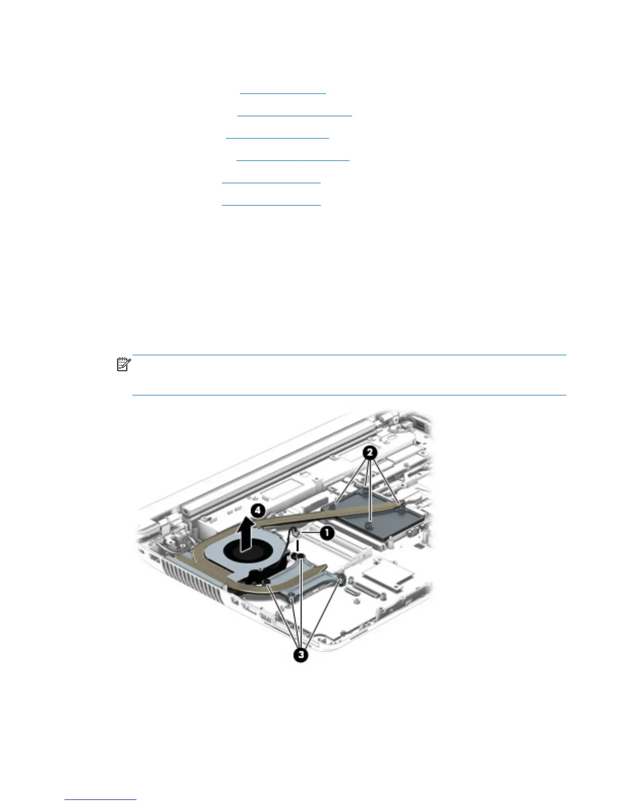
Remove the fan/heat sink assembly:
1. Disconnect the fan cable (1) from the system board.
2. Following the 1 through 4 sequence stamped into the processor heat sink, loosen the four Phillips
captive screws (2) that secure the processor heat sink to the system board.
3. Following the 5 through 8 sequence stamped into the graphics board heat sink, loosen the four
Phillips captive screws (3) that secure the graphics board heat sink to the system board.
4. Remove the fan/heat sink assembly (4).
NOTE: Due to the adhesive quality of the thermal material located between the fan/heat sink
assembly and the system board components, it may be necessary to move the fan/heat sink
assembly from side to side to detach it.
Component replacement procedures
91
 Loading...