Installation checklist 17
3 Installing the enclosures
Installation checklist
The following table outlines the steps required to install the enclosures and initially configure the system. To ensure a
successful installation, perform the tasks in the order they are presented.
1
The SMU is introduced in “Accessing the SMU” (page 38). See the SMU Reference Guide or online help for additional information.
Connecting controller and drive enclosures
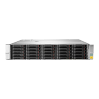
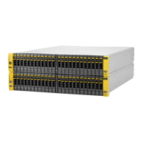
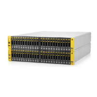
MSA 1050 controller enclosures support up to four enclosures (including the controller enclosure). You can cable drive
enclosures of the same type or of mixed LFF/SFF model type.
The firmware supports both straight-through and fault-tolerant SAS cabling. Fault-tolerant cabling allows any drive
enclosure to fail—or be removed—while maintaining access to other enclosures. Straight-through cabling does not
provide the same level of fault-tolerance as fault-tolerant cabling, but does provide some performance benefits as well as
ensuring that all disks are visible to the array. Fault tolerance and performance requirements determine whether to
optimize the configuration for high availability or high performance when cabling. MSA 1050 controller enclosures
support 12 Gb/s disk drives downshifted to 6 Gb/s. Each enclosure has an expansion port using 6 Gb/s SAS lanes. When
connecting multiple drive enclosures, use fault-tolerant cabling to ensure the highest level of fault tolerance.
For example, the illustration on the left in Figure 11 (page 20) shows controller module 1A connected to expansion
module 2A, with a chain of connections cascading down (blue). Controller module 1B is connected to the lower expansion
module (4B) of the last drive enclosure, with connections moving in the opposite direction (green).
Table 2 Installation checklist
Step Task Where to find procedure
1. Install the controller enclosure and optional
drive enclosures in the rack, and attach the
bezel or ear caps.
See the racking instructions poster.
2. Connect the controller enclosure and LFF/SFF
drive enclosures.
See “Connecting controller and drive enclosures” (page 17).
3. Connect power cords. See the quick start instructions.
4. Test enclosure connections. See “Testing enclosure connections” (page 21).
5. Install required host software. See “Host system requirements” (page 23).
6. Connect data hosts. See “Connecting the enclosure to data hosts” (page 23).
If using the optional Remote Snap feature, also see
“Connecting two storage systems to replicate volumes”
(page 28).
7. Connect remote management hosts. See “Connecting remote management hosts” (page 27).
8. Obtain IP values and set management port IP
properties on the controller enclosure.
See “Obtaining IP values” (page 33).
See “Connecting to the controller CLI port” (page 32); with
Linux and Windows topics.
9. Perform initial configuration tasks
1
:
• Sign in to the web-based Storage
Management Utility (SMU).
• Initially configure and provision the storage
system using the SMU.
Topics below correspond to bullets at left:
See “Getting Started” in the HPE MSA 1050/2050 SMU
Reference Guide.
See “Configuring the System” and “Provisioning the System”
topics (SMU Reference Guide or online help).
 Loading...
