Front panel LEDs 59
MSA 1050 Array LFF or supported 12-drive expansion enclosure
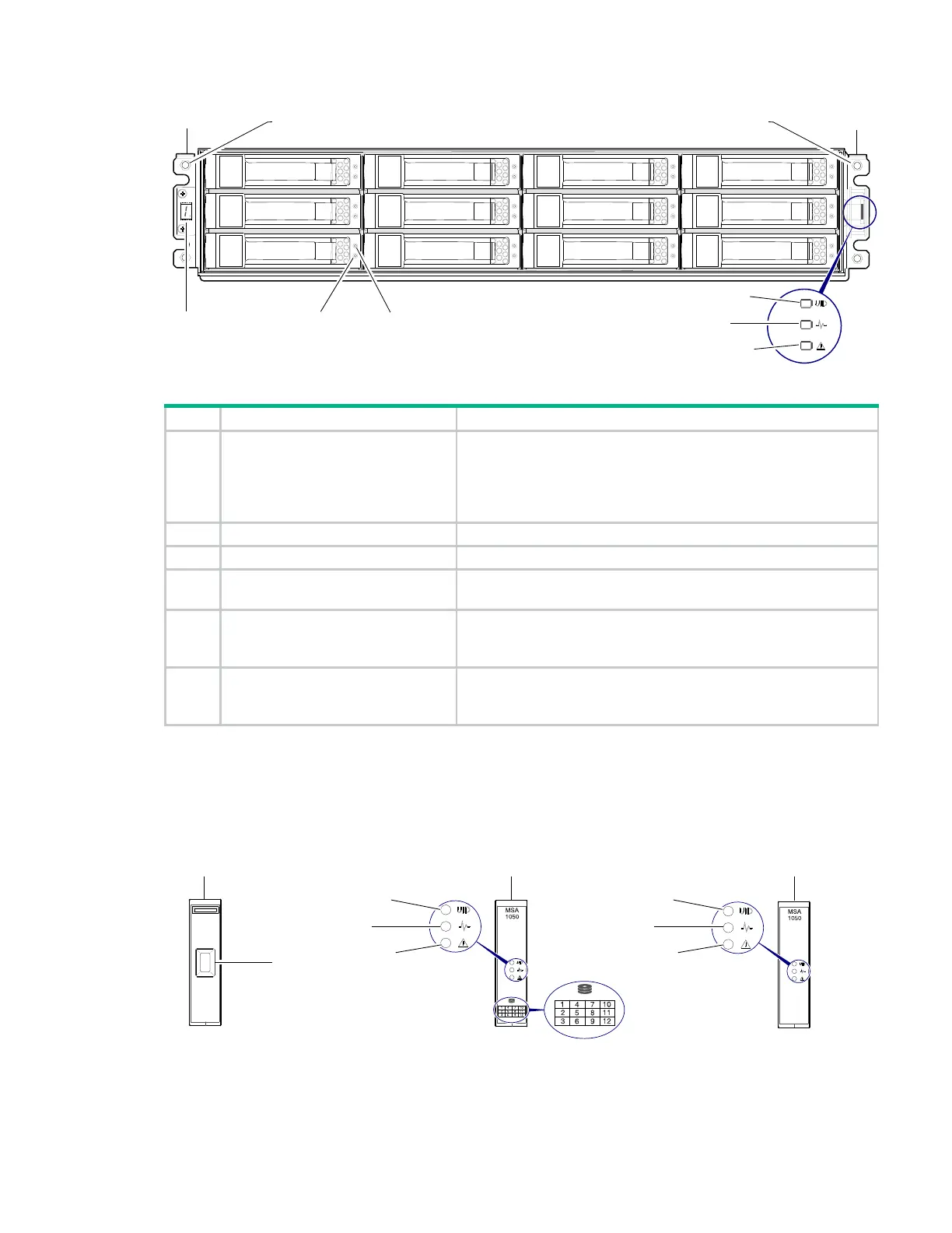
Figure 24 LEDs: MSA 1050 Array LFF or supported 12-drive expansion enclosure: front panel
Ear covers
Ear covers can be used instead of the enclosure bezel. Figure 25 callouts apply to the table for Figure 24. See Figure 22
(page 57) for detail views of mounting sleeve attachment to ball studs located on left and right ears.
Figure 25 Ear covers option to enclosure bezel
1 2 3
Left ear
Right ear
4
5
6
1
2
3
4
5
6
7
8
9
10
11
12
Notes:
Integers on disks indicate drive slot numbering sequence.
The enlarged detail view at right shows LED icons from the bezel that correspond to chassis LEDs.
Bezel icons for LEDs
Ball stud (two per ear flange) Ball stud (two per ear flange)
The detail view locator circle (above right) identifies the ear kit that connects to LED light pipes in the bezel (or ear cover).
LED Description Definition
1 Enclosure ID Green — On
Enables you to correlate the enclosure with logical views presented by
management software. Sequential enclosure ID numbering of controller
enclosures begins with the integer 1. The enclosure ID for an attached drive
enclosure is nonzero.
2 Disk drive Online/Activity See “Disk drive LEDs” (page 60).
3 Disk drive Fault/UID See “Disk drive LEDs” (page 60).
4 Unit Identification (UID) Blue — Identified.
Off — Identity LED off.
5 Heartbeat Green — The enclosure is powered on with at least one power supply
operating normally.
Off — Both power supplies are off; the system is powered off.
6 Fault ID Amber — Fault condition exists. The event has been identified, but the
problem needs attention.
Off — No fault condition exists.
Left ear cover LFF 12-drive right ear cover SFF 24-drive right ear cover
1
4
5
6
Disk slot numbers
4
5
6
Callout numbers pertain to chassis LED descriptions in the table above.