Do you have a question about the HPE StoreFabric M-Series and is the answer not in the manual?
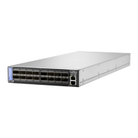
Provides a general overview of the HPE StoreFabric M-Series SN2000M switch systems.
Details the maximum throughput and interface speed capabilities of the switch models.
Lists the management interfaces, power supply units, and fans for each system model.
Directs users to the HPE website for a full list of system features.
Indicates where to find certification lists for the systems on the HPE website.
Provides part numbers and ordering details for the available switch systems.
Outlines essential safety warnings and references to specific country warnings.
Guides on the mechanical, power, and thermal precautions for system installation.
Explains airflow direction requirements and considerations for system installation.
Lists the system components included in the package for unpacking and verification.
Describes different methods for mounting the switch systems into a 19-inch rack.
Details the installation procedure for the static rail kit used with the SN2700M.
Explains the installation of the telescopic rail kit for SN2700M systems.
Provides instructions for installing the static rail kit for SN2410M/SN2410bM.
Covers side-by-side mounting for SN2100M/SN2010M using specific rail kits.
Guides on inserting and removing cables, and LED indicators for physical connections.
Lists compatible modules and cables for different switch models.
Explains how to use breakout cables to split ports for different speeds.
Describes the procedure for powering on the switch system for the first time.
Guides on initial system configuration and bringing the switch online.
Details network attribute configuration using the MLNX-OS CLI or wizard.
Explains how to replace Field Replaceable Units (FRUs) like power supplies and fans.
Provides instructions for extracting and replacing power supply units in the systems.
Details the procedure for removing and inserting fan modules.
Lists the types of interfaces supported by the switch systems, including Ethernet and USB.
Describes the data interfaces, primarily QSFP28 connectors, and transceiver support.
Explains how to manually configure Ethernet port speeds from 10GbE to 100GbE.
Details the RS232 console port used for initial configuration and debugging.
Covers the RJ45 Ethernet management (MGT) ports for remote access and configuration.
Explains the use of the USB port for software upgrades and file management.
Describes the location and function of the system's reset button for rebooting or password reset.
Introduces the system's status and port LEDs used for hardware event notification.
Provides a detailed overview of the system's LEDs.
Explains the meaning of different LED symbols and their normal conditions.
Details the System Status LED behavior for different conditions like booting, normal operation, or errors.
Describes the Fan Status LED behavior indicating the health of the fan modules.
Explains the Power Supply Status LEDs for indicating PSU health and connection status.
Describes the UID LED used for identifying a specific system within a cluster.
Explains the Bad Port LED, which indicates symbol errors on the system's ports.
Details the behavior of port LEDs in Ethernet system mode, indicating link status and traffic.
Guides on how to upgrade the MLNX-OS software and switch firmware.
Provides instructions for upgrading the MLNX-OS software from the HPE Support website.
Explains that firmware updates are managed through the MLNX-OS software.
Offers guidance on diagnosing and resolving common system issues based on LED indicators and symptoms.
Provides detailed specifications for the SN2700M switch model, including mechanical, environmental, and power details.
Lists the detailed specifications for the SN2410M and SN2410bM switch models.
Presents the detailed specifications for the SN2100M switch model.
Outlines the detailed specifications for the SN2010M switch model.
Lists accessory and replacement part numbers (OPNs) for various switch systems.
Defines thermal warning, critical, and emergency thresholds that affect switch operation.
Details the QSFP interface pin assignments for SFP28 connections.
Provides rear view pin placement details for SFP28 modules.
Illustrates the pinout for the RJ45 to DB9 harness cable used for console connections.
Provides step-by-step instructions for safely disassembling the system from a rack.
Guides on the responsible and environmentally friendly disposal of the product according to WEEE directives.
Lists safety notices specific to Nordic countries.
Provides detailed installation safety warnings in English, covering weight, electric shock, and over-temperature.
Includes safety warnings and installation instructions in Hebrew.
Guides on how to access HPE support resources, documentation, and services.
| Product Series | M-Series |
|---|---|
| Typical Power Consumption | Varies by model and configuration |
| Category | Switch |
| Management | CLI, SNMP, Web GUI |
| Operating Temperature | 0°C to 40°C |
| Power Supply | Redundant power supplies |
| Form Factor | 1U, 2U |
| Protocols | Ethernet, VXLAN |
| Virtualization Support | Yes |
| Redundancy | Redundant power supplies |
| Ports | Varies by model (e.g., 32, 48, 64 ports) |