Installation
17
User Manual
2. Pay attention to the air flow consideration within the system and rack - refer to “Air Flow” on
page 17.
3. Make sure that none of the package contents is missing or damaged - see “Package Contents”
on page 17.
4. Mount the system into a rack enclosure - see “19” Systems Mounting Options” on page 18.
5. Power on the system - refer to “Initial Power On” on page 46.
6. Perform system bring-up - see “System Bring-Up” on page 48.
7. [Optional]: FRU replacements are described in Section 2.9 on page 53.
2.3 Air Flow
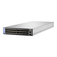
All HPE StoreFabric M-Series switches have back-to-front air flow, as shown in Figure 8
Figure 8: Air Flow Direction Marking - Power Side Inlet to Connector Side Outlet
2.4 Package Contents
Before installing your new system, unpack it and check against the parts list below that all the
parts have been sent. Check the parts for visible damage that may have occurred during shipping.
The SN2700M and SN2410M/SN2410bM package content is as follows:
• 1 – System
• 1 – Rail kit
• 1 – Power cable for each power supply unit – Type C13-C14
• 1 – Cable retainer for each power supply unit
• 1 – DB9 to RJ-45 2m harness
The SN2100M/SN2010M package content is as follows:
• 1 – System
• 1 – Power cable for each power supply unit – Type C13-C14
The following information does not apply to SN2100M/SN2010M. In the SN2100M/
SN2010M systems, the fan units are non-replaceable.
All servers and systems in the same rack should be planned with the same airflow
direction.
All FRU components need to have the same air flow direction. A mismatch in the air
flow will affect the heat dissipation.
 Loading...