Chapter 7 Detailed Function Introduction Shenzhen Hpmont Technology Co., Ltd.
-34- HD09 Series User Manual V1.1
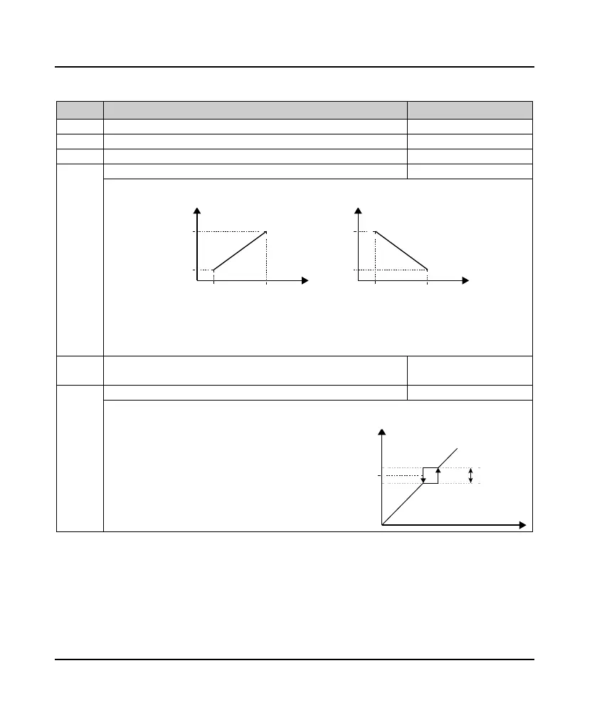
7.6 F05: External Given Curve Parameters
Ref. Code Function Description Setting Range [Default]
F05.01 Line min. given 0.0 - F05.03 [0.0%]
Line min. given corresponding
F05.03 Line max. given F05.01 - 100.0 [100.0%]
Line max. given corresponding
F05.01 - F05.04 define AI and DI line, positive feature (left below diagram) and negetive feature (right below
diagram) can be realized.
In diagram:
• AI is analogue preset, DI4 is impuse preset.
• When AI analogue preset is 100%, 10V or 20mA is correspionding.
• DI4 impulse preset is 100%, F16.17 (DI4 input terminal Max. impulse frequency) is corresponding.
F05.17 Hopping frequency F00.09 - Max. frequency
F05.20 Hopping frequency range 0.0 - 30.0 [0.0Hz]
Hopping frequency setting can let converter output frequency avoid mechanical load resonance frequency
points.
• Converter’s setted frequency can hop running near
F05.17 point by right diagram.
• During Acc. and Dec. running process, go through
hopping frequency area in continous output frequency,
but can not constant running in hpping arez.
• Frequency setting is hopping and output is continous.
F05.01 F05.03
F05.04
F05.02
Setting
corresponding value
F05.01 F05.03
F05.02
F05.04
Setting
corresponding value
AI/DI4 AI/DI4
Setting frequency after calculating
Setting frequency
F05.20
F05.17
 Loading...

