26
The chart below represents the various system design temperature rise through the boiler, along with
respective flows and friction loss which will aid in circulator selection.
Table 3 – Temperature Rise Chart
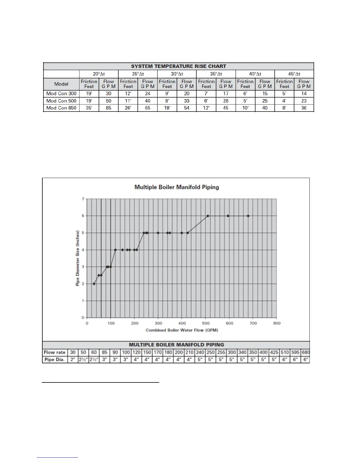
The chart below represents the combined flow rates and pipe sizes when using multiple boilers to design
the manifold system for the primary circuit. To size, simply add up the number of boilers and the required
flow rates for the system design temperature.
Example: (5) Mod Con 300 boilers with a design of 30
o
F temperature rise with each boiler having an
individual flow rate of 20 GPM. To correctly size the manifold feeding these boilers, you would need a
pipe size of 3”.
Figure 12 – Multiple Boiler Manifold Piping
I. FILL AND PURGE HEATING SYSTEM
• Attach the hose to balance and purge hose connector or drain valve and run hose to nearest
drain.
• Close the other side of the balance and purge valve or the shut off valve after the drain.
 Loading...


