LP-179 Rev. 6.7.16
34
Part 9 - Start-Up Procedure
FOR YOUR OWN SAFETY READ BEFORE OPERATING
1. This water heater does not have a pilot. It is equipped with
an ignition device which automatically lights the burner. Do
not try to light the burner by hand.
2. BEFORE OPERATING: Smell all around the water heater
area for gas. Be sure to smell next to the oor because some
gas is heavier than air and will settle on the oor.
WHAT TO DO IF YOU SMELL GAS
• Do not try to light any water heater.
• Do not touch any electric switch, do not use any phone
in your building.
• Immediately call your gas supplier from a neighbor’s
phone. Follow the gas suppliers’ instructions.
• If you cannot reach your gas supplier, call the re
department.
• Turn o the gas shuto valve (located outside the water
heater) so that the handle is crosswise to the gas pipe.
If the handle will not turn by hand, don’t try to force
or repair it, call a qualied service technician. Force or
attempted repair may result in a re or explosion.
4. Do not use this water heater if any part has been under
water. Immediately call a qualied service technician to
inspect the water heater and to replace any part of the control
system and any gas control that has been damaged.
5. The water heater shall be installed so the gas ignition
system components are protected from water (dripping,
spraying, rain, etc.) during water heater operation and
service (circulator replacement, condensate trap, control
replacement, etc.)
Failure to follow these instructions could result in property
damage, serious personal injury, or death.
A. Operating Instructions
If you smell gas, STOP. Follow listed safety instructions above.
If you do not smell gas, follow the next steps.
1. Make sure tank is full with cold water and purge all piping.
To assure adequate purging, open all hot water faucets.
Ensure the water heater is full of water before ring the
burner. Failure to do so will damage the heater. Such damage
IS NOT covered by warranty, and could result in property
damage, serious personal injury, or death.
2. Turn on all electric power to water heater.
3. Adjust the temperature set point of the heater to the
desired level. The factory default setting is 119
o
F. If changes
are necessary, follow “Overall Water Heater and Control
Operation” in this section.
4. If the water heater fails to start, refer to the Troubleshooting
section in the back of this manual.
B. Overall Water Heater and Control Operation
To adjust the temperature of stored water, press and hold
S3 for 2 seconds. The rst item is du: Water Temperature Set
Point - factory set at 119
o
F. Adjust down by pressing S1 to
a temperature as low as 95
o
F. Adjust up as high as 160
o
F by
pressing S2. Press S3 again to display dh: Dierential, which is
factory set at 7
o
F and adjustable down to1
o
F by pressing S1 and
up to 18
o
F by pressing S2. NOTE: Due to the highly advanced
control on this water heater, which compensates for varying
inlet water temperature, the actual dierential temperature
may vary slightly from the setting. Press S3 again to display
the factory default temperature measurement in Fahrenheit.
Change the default to Celsius by pressing S1. When nished,
press S3 one nal time to place unit back in operation. The
control automatically restarts if no key is pressed for 2 minutes.
NOTE: If Outdoor Reset is used, Function 9 must match the du
setting. Failure to match Function 9 and the du setting will result
in improper water heater operation.
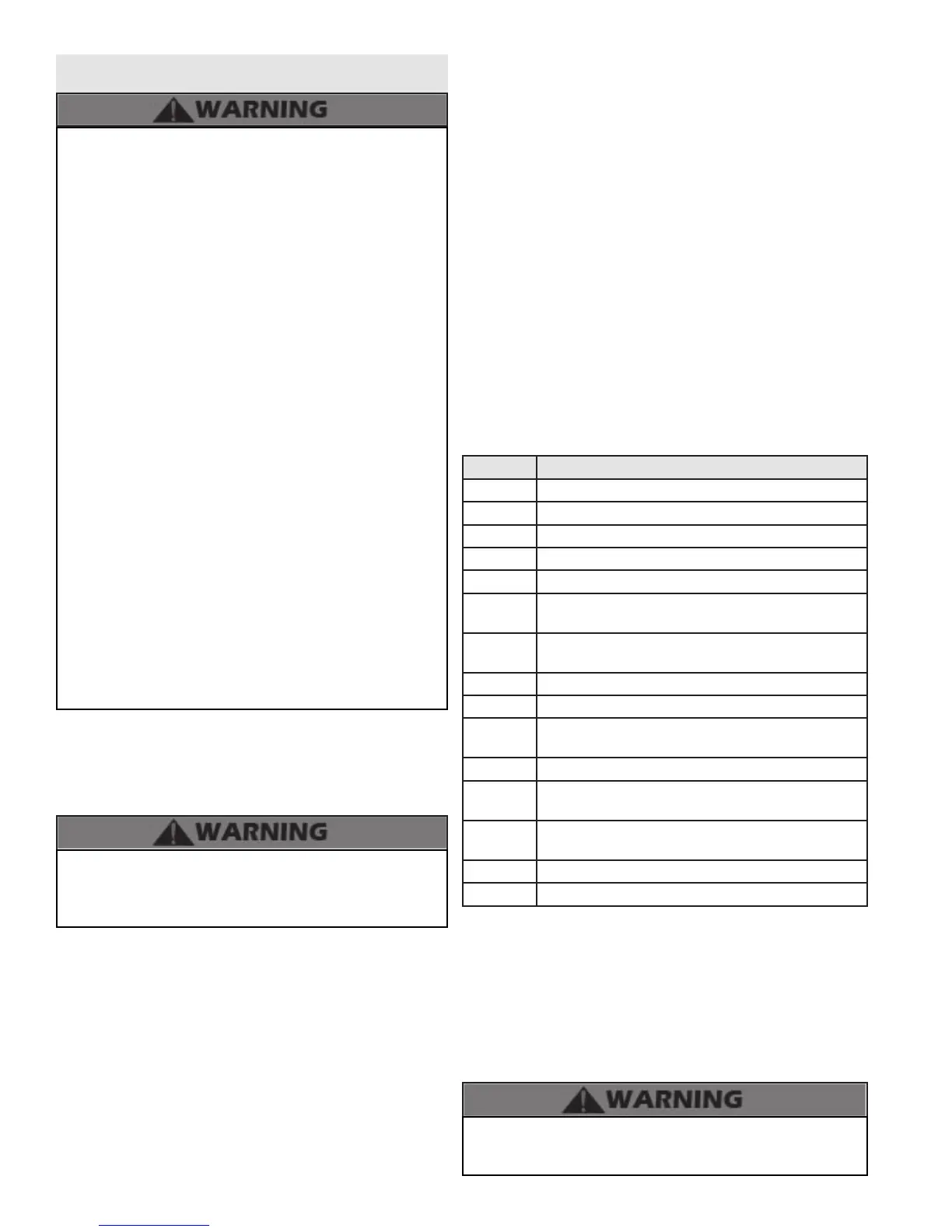
C. Status Menu
Installers are also able to check the current status of the heater
parameters by pressing S4 for 3 seconds. Once activated, the
display will show d1 alternating with the actual upper supply tank
temperature. Actual values are displayed for each function. To
view the next value, simply press S4 to go to the next displayed
value. Listed below are the values which can be displayed. These
values cannot be changed. To exit this menu, press S3 to resume
normal operation.
Function Value
d1 Actual temperature from upper tank sensor
d2 Actual temperature from lower tank sensor
d3 0 - Not Used
d4 308 - Not Used
d5 Outdoor Sensor
d6
Actual Fan Speed divided by 10 (Example: If fan speed
displayed is 410 x 10 = 4100 RPM actual fan speed)
d7
Actual Ionization Current read from ame rectication
probe
d8 0 - Not Used
d9 1 - Not Used
d10
Actual status of bus communication - co = connected,
nc = not connected
d11 32 - Not Used
d12
Power on hours in thousands (display will not read until
100 hours)
d13
Total water heating hours in thousands (display will not
read until 100 hours)
d14 0 - Not Used
d15 Passed ignition attempts in thousands
Table 12 - Status Menu Functions and Values
D. Outdoor Reset
NOTE: The outdoor reset function cannot be used if the 0-10
volt function is enabled.
This unit is supplied with outdoor reset wire connection
terminals. When an outdoor sensor (p/n 7250P-319) is
connected, operation of the unit immediately changes. Refer
to the following steps to properly set up the unit with an outdoor
sensor.
An ASSE 1017 thermostatic mixing valve MUST be installed
when using outdoor reset. Failure to do so could result in
substantial property damage, severe personal injury, or death.