Figures
Figure 2-1 Network application of the HG552d ....................................................................... 7
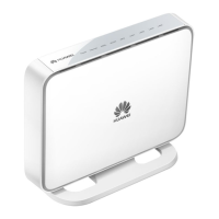
Figure 2-2 Indicators .................................................................................................................. 8
Figure 2-3 Interfaces and buttons ............................................................................................10
Figure 3-1 Connecting the HG552d ........................................................................................12
Figure 3-2 Connecting the USB Interface...............................................................................13
Tables
Table 2-1 Description of the elements for the network application diagram........................... 8
Table 2-2 Meanings of the indicators ......................................................................................... 9
Table 2-3 Functions of the interfaces and buttons ...................................................................10
Table 4-1 Requirements on PC settings ...................................................................................14