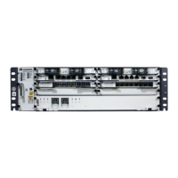
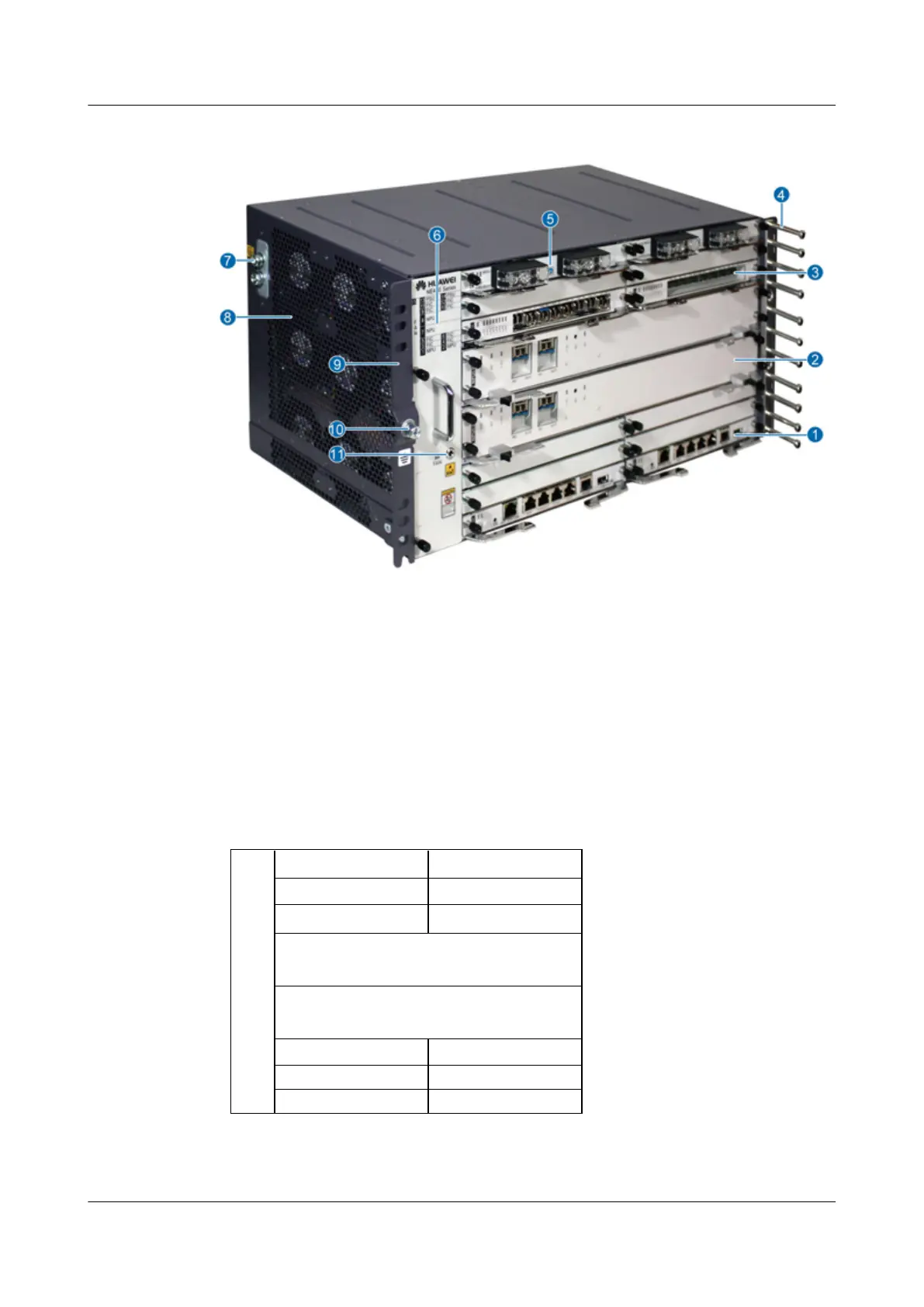
Figure 2-3 Outline and parts of the NE40E-X2
1. MPU 2. NPU 3. PIC 4. Cabling rack
5. PSU 6. Fan Module 7. Grounding Terminal 8. Air intake vent
9. Rack mounting ear 10. Grounding Terminal 11. ESD jack
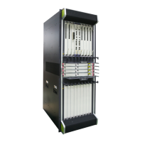
2.1.6 Number of Main Parts and Slot Layout of the NE40E-X2
Figure 2-4 shows the slot layout of the NE40E-X2.
Figure 2-4 Slot layout of the NE40E-X2
15
FAN
13 PSU 14 PSU
11 FIC 12 FIC
10 FIC/HIC
9 FIC/HIC
8 NPU
7 NPU
5 FIC/HIC 6 FIC/HIC
4 FIC3 FIC
1 MPU 2 MPU
HUAWEI NE40E-X1 & NE40E-X2 Universal Service
Router
Hardware Description 2 NE40E-X2 Hardware Description
Issue 02 (2011-09-10) Huawei Proprietary and Confidential
Copyright © Huawei Technologies Co., Ltd.
25
 Loading...