No. Label Ēʲì²ÑÊ Single SUN2000
Scenario
SUN2000 Cascading
Scenario
5 GND GND of the
enable
signal/12V/DI1/
DI2
Used for connecting to GND of the enable
signal/12V/DI1/DI2.
6 EN+ Enable signal
+/12V+
Used for connecting to the enable signal of
the battery and the 12V positive signal.
7 DI1 Digital input
signal 1+
Used for connecting to the DI1 positive
signal. It can be used for connecting to the
DRM0 scheduling signal or reserved for the
rapid shutdown signal.
8 DI2 Digital input
signal 2+
Used for connecting to the DI2 positive
signal. It can be reserved for the feedback
signal of the Backup device.
NO TE
For details about how to connect signal cables, see the SUN2000L-(2KTL-5KTL) and
SUN2000-(2KTL-6KTL)-L1 Battery and Smart Power Sensor Quick Guide. You can also
scan the QR code to obtain the document.
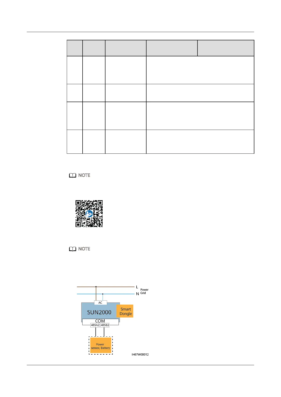
Communication Networking Mode
NO TE
The smart power sensor and Smart Dongle must be connected to the same SUN2000.
ɲ ^²ÊªÃ^kEǂǀǀǀäÊà²Ñä
Figure 5-19 Single SUN2000
SUN2000-(2KTL-6KTL)-L1
User Manual 5 Electrical Connection
Issue 03 (2020-09-15) Copyright © Huawei Technologies Co., Ltd. 50
 Loading...