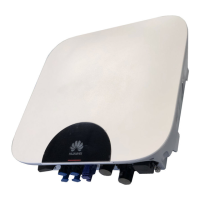
Figure 5-19 Communications cable ports
Table 5-6 COM port denition
No. Label Denition Description
1 OUT+ 12V_OUT+ Battery enabling signal
2 OUT- 12V_OUT–
3 A1 RS485A1 Southbound RS485 port for
connecting to the battery RS485
port
4 B1 RS485B1
5 A2 RS485A2 Connects to the COM1 signal
port on the SmartLogger (skip
this step when there is no CT
cable; only for an inverter with a
CT cable)
6 B2 RS485B2
7 A3 RS485A3 Connects to the COM2 signal
port on the SmartLogger or
cascades inverters
8 B3 RS485B3
Procedure
Step 1 Prepare communications cable terminals and route them into the maintenance
compartment through the communications cable hole at the bottom of the
SUN2000.
● The core wires are completely inserted into the cable hole.
● Ensure that the communications cable is securely connected.
● Ensure that the cable is not twisted.
SUN2000-4.95KTL-JPL1
User Manual 5 Electrical Connections
Issue 05 (2023-02-17) Copyright © Huawei Technologies Co., Ltd. 56
 Loading...