Step 3 Turn on the AC switch between the inverter and the power grid.
Step 4 Turn on the DC switch (if any) between the PV strings and the inverter.
Step 5 (Optional) Remove the knob locking screw next to the DC switch on the inverter.
Step 6 Set the DC switch on the inverter to ON.
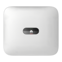
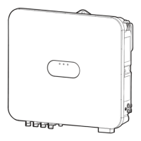
Step 7 Observe the LED indicators to check the status of the inverter.
Table 7-1 LED indicators
Category Status Description
Running
indication
LED1 LED2 –
Steady green Steady green The inverter is running in
grid-tied state.
Blinking green
slowly (on for 1s
and o for 1s)
O The DC is on and the AC is
o.
Blinking green
slowly (on for 1s
and o for 1s)
Blinking green slowly (on for
1s and o for 1s)
Both the DC and AC are on,
and the inverter is o-grid.
O Blinking green slowly (on for
1s and o for 1s)
The DC is o and the AC is
on.
Steady yellow Steady yellow The inverter is running in o-
grid state.
Blinking yellow
slowly
O The DC is on and the inverter
has no output in o-grid
state.
Blinking yellow
slowly
Blinking yellow slowly The inverter is in o-grid
overload state.
O O Both the DC and AC are o.
Blinking red fast
(on for 0.2s and
o for 0.2s)
– There is a DC environmental
alarm, such as String Voltage
High, String Reverse
Connection, or Low
Insulation Resistance.
– Blinking red fast (on for 0.2s
and o for 0.2s)
There is an AC environmental
alarm, such as Grid
Undervoltage, Grid
Overvoltage, Grid
Overfrequency, or Grid
Underfrequency.
Steady red Steady red A fault exists.
SUN2000-(8K, 10K)-LC0 Series
User Manual 7 Power-On and Commissioning
Issue 01 (2023-09-15) Copyright © Huawei Digital Power Technologies Co., Ltd. 76
 Loading...


