TP482000B V300R002C03 Telecom Power
(TP482000B-N20B1, TP482000B-N20B2,
TP481200B-N20B1, and TP481200B-N20B2)
User Manual
Copyright © Huawei Technologies Co., Ltd.
Step 7 Set DIP switch S1 for the new main control board based on the recorded information.
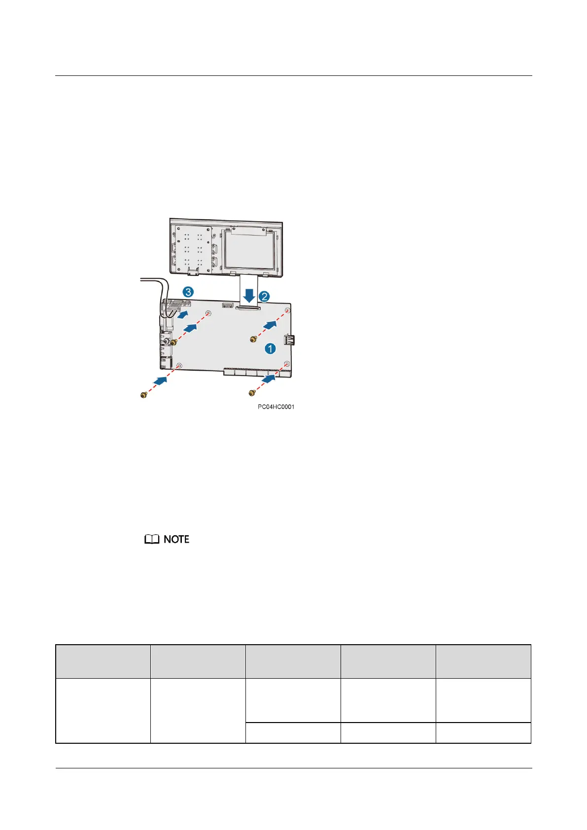
Step 8 Install the new main control board, as shown in Figure 7-6.
1. Place the new main control board in position and tighten the screws.
2. Reconnect the communications cables and signal cables to the new main control board
based on the recorded information.
3. Reconnect the power cable to the J12 port on the main control board.
Figure 7-6 Installing a main control board
Step 9 Place the SMU cover in position and tighten the screws.
Step 10 Reconnect the cables to the RJ45 ports on the SMU based on the recorded information.
Step 11 Disconnect the ground cable for the ESD wrist strap, and take off the ESD wrist strap and
ESD gloves.
Step 12 Import the SMU configuration file that you have backed up.
If data backup cannot be completed in Step 1, skip Step 12 and set the SMU parameters again by
referring to the installation guide.
After you import the configuration file, the SMU restarts.
1. Connect the network cable to the FE port on the SMU, and set the SMU IP address to the
same network segment as the PC IP address on the LCD. Table 7-2 lists the menus.
Table 7-2 Setting the SMU IP address
Apply to the network
administrator for an
address.