14
Mounting Sensors DSP700 Series Wireless Wheel Alignment Sensors
NOTE: The sensor mounting shaft must be fully inserted into the sensor
shaft mounting hole.
When the sensor shaft is fully inserted into the sensor shaft mounting hole, the adaptor
locking lever should be rotated clockwise into the locked position using firm hand
pressure. Tools should not be used to force the adaptor locking lever.
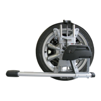
Wheel Adaptor 175-321-1 with Ratchet Adaptor Locking Lever
Rotate the adaptor locking lever clockwise to tighten. If upper casting prevents rotation of
lever, either expand adaptor to move upper casting or re-position the adaptor locking
lever by lifting up to disengage, rotating counter-clockwise, and lowering to re-engage.
Proceed until the shaft is locked tight to adaptor.
With shaft fully locked, re-position the lever to the 9 o’clock position by lifting the adaptor
locking lever up to disengage, rotating to 9 o’clock, and lowering to re-engage.
Re-position lever to 9 o’clock
The adaptor locking lever in the 9 o’clock position eliminates possible contact with upper
casting or sensor during alignments.
 Loading...