24
25
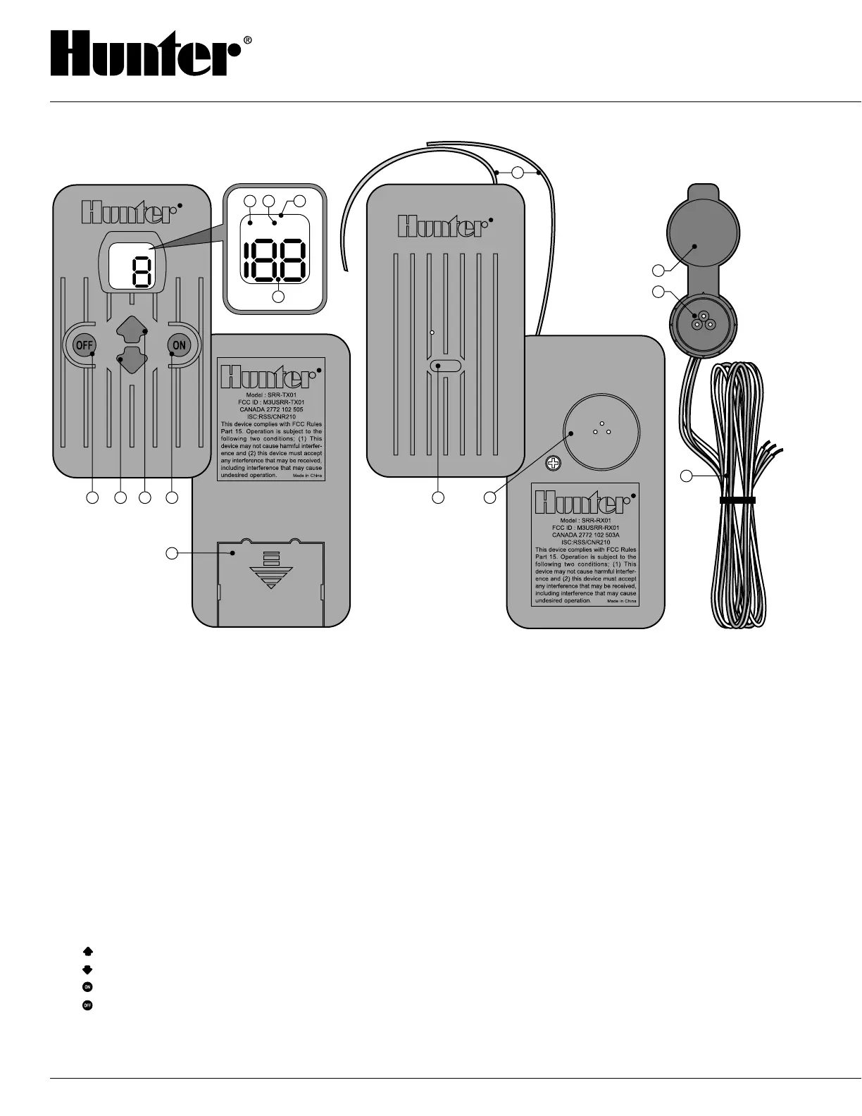
SRR COMPONENTS
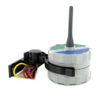
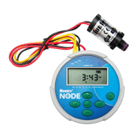
RECEIVER
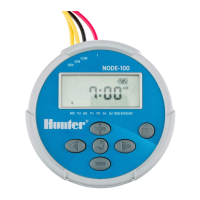
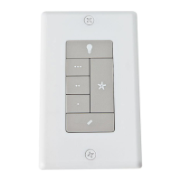
TRANSMITTER
A. LCD Display
1. Run Time – Indicates the Station Run Time is
being set when flashing.
2. Transmit – Indicates that the Transmitter is
transmitting the programmed data to the receiver.
3. Main Display – Indicates various times and values.
Number – Indicates either Station Run Time (1 to
30) or Station number (1 to 48).
On – Indicates Transmitter is turning on a
particular station.
Off – Indicates Transmitter is turning off a
particular station.
Program (A, B, C) – Indicates program selected.
4. Address – Indicates that a new address for
transmitting between the Transmitter and the
Receiver is being set.
B. Control Buttons
5. – Increases the selected flashing display.
6. – Decreases the selected flashing display.
7. – Selects the selected flashing display.
8. – Cancels the selected flashing display.
C. Other
9. Battery Cover – Covers compartment for 9-volt
alkaline battery.
RECEIVER
10. Control Button – Hold button down when
plugging Receiver into SmartPort® when
programming a new address.
11. SmartPort
®
Outlet (Male) – Outlet on back of
Receiver that plugs into the SmartPort® harness.
12. Antenna – Receives signals from Transmitter
from up to 450'.
SmartPort
®
13. SmartPort
®
Outlet (Female) – Outlet on front of
SmartPort
®
that plugs into the SRR Receiver or
other Hunter product.
14. Rubber Cover – Protects SmartPort
®
from dirt
and weather.
15. Control Wires – Red, white, and blue wires that
connect to the terminal strip area of the
controller.
TRANSMITTER
SmartPort
®