18 – English
6 Basic dismantle/assembly
Basic dismantle/assembly
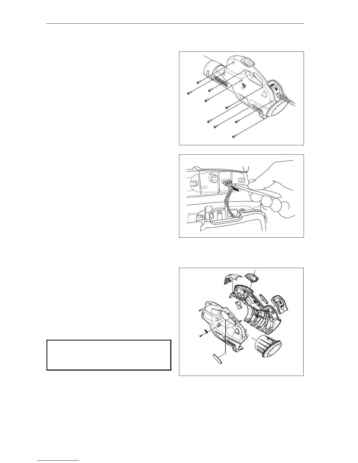
6.3 Chassis (536LiBX)
Loosen the screws (x9) and lift o the left chassis
half (A) and ventilation cover (B).
See gure 3b.
Loosen the service cable fastened to the left chas-
sis half. Use tweezers or a small pair of pliers, see
gure 3c.
Cleaning and inspection
Carefully clean and inspect the chassis halves
(including hand grip), ventilation covers and the
eyelet. Parts must be replaced if cracked or show-
ing signs of other defects. Always use original
spare parts.
See gure 4b.
Assemble in the reverse order.
Tightening torque 1.9±0.1 Nm.
NOTE!
It should be easy to put together the chassis
halves. Make sure cables and such are
positioned correctly if this is dicult.