30 – English
Repair instructions
6
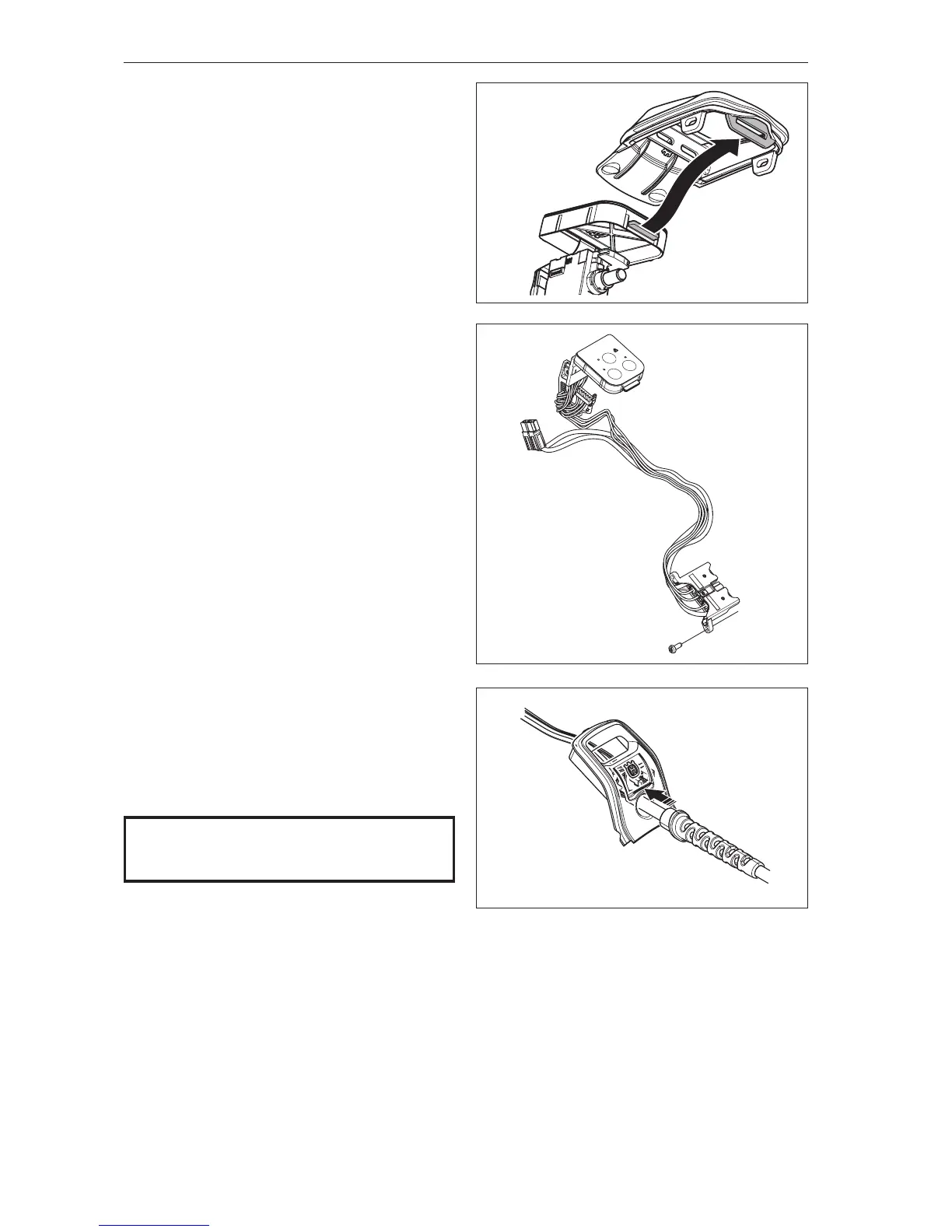
Unhook the cover from the keypad.
See gure 27
7
Dismantle the control unit.
See Chapter 7.10.
8
Dismantle the main switch.
See Chapter 7.12.
Cleaning and inspection
Clean and inspect all parts. They must always be
replaced with new ones if cracked or showing signs
of other defects. Always use original spare parts.
See gure 28
7.9 Assembling the main cable
1
Assemble the main switch.
See Chapter 7.13.
2
Assemble the control unit.
See Chapter 7.11.
3
Hook the cover onto the keypad.
See gure 27
4
(536LiBX)
Pull the main cables through the display cover.
Ensure there is no play between the cables and the
cover. See gure 28b.
Place all cables (in their attachments), control unit,
main switch and main cables into the chassis.
See gure 26a (436LiB, 536LiB).
See gure 26b (536LiBX).
5
(436LiB, 536LiB)
Fasten the screws (A) for the battery contact.
Tightening torque 0.7±0.1 Nm.
See gure 25a (436LiB, 536LiB).
Fasten the screws holding the battery cable.
Tightening torque 1.9±0.1 Nm.
See gure 25b (536LiBX).
Fig 27
Fig 28
NOTE!
Ensure cables, etc., are positioned correctly
to avoid pinching.
6
Assemble the cover over the electronics.
Tightening torque 0.7±0.1 Nm.
See gure 24
7
Assemble the motor housing/blow pipe.
See Chapter 7.7.
8
Assemble the contact spring.
See Chapter 7.5.
Fig 28b