English – 27
Fig 22
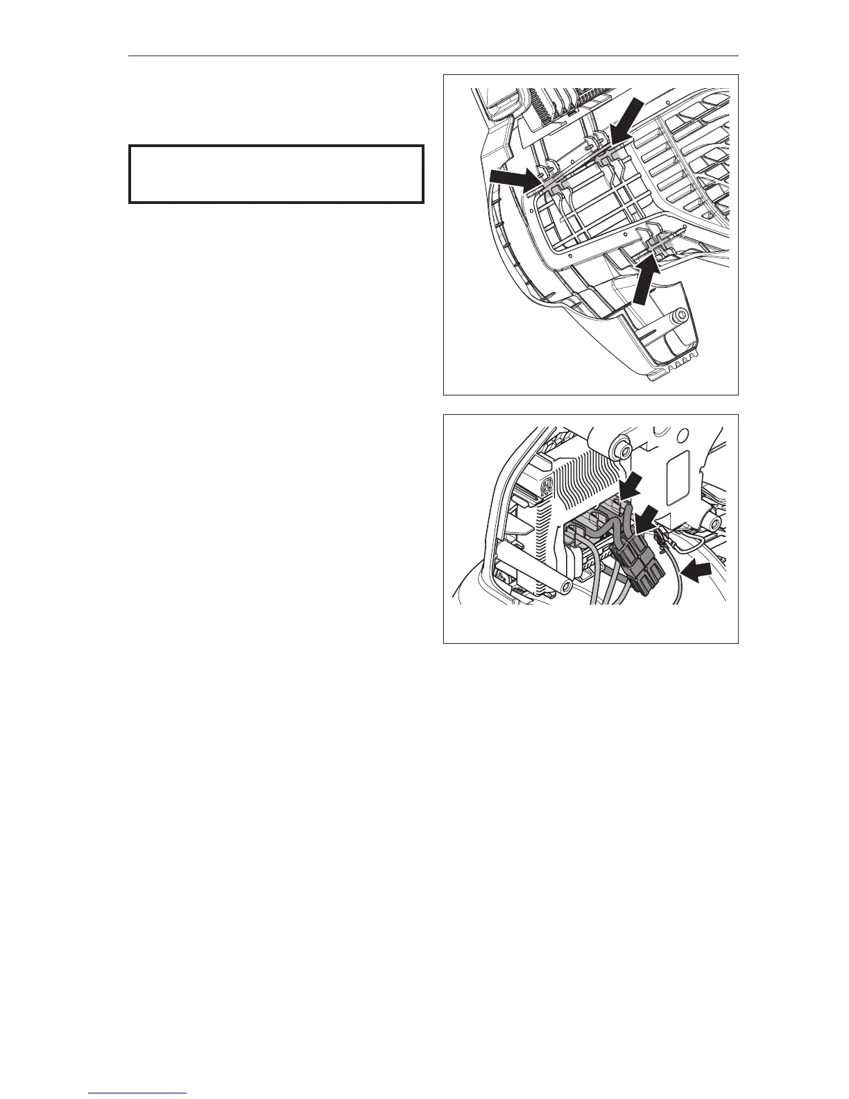
7
Place the blow pipe and motor housing in the chassis.
Make sure the rubber pads are positioned correctly.
See gure 22
8
Couple connector (A) to the control unit. Take care
not to damage the connector (B) with cables.
Couple connector (C) to the contact spring.
NB! Do not pull the wires.
See gure 23
NOTE!
Ensure cables, etc., are positioned correctly
to avoid pinching.
Repair instructions
Fig 23
C
A
B