User Manual
Rev 9.0 Page 17 HV Diagnostics
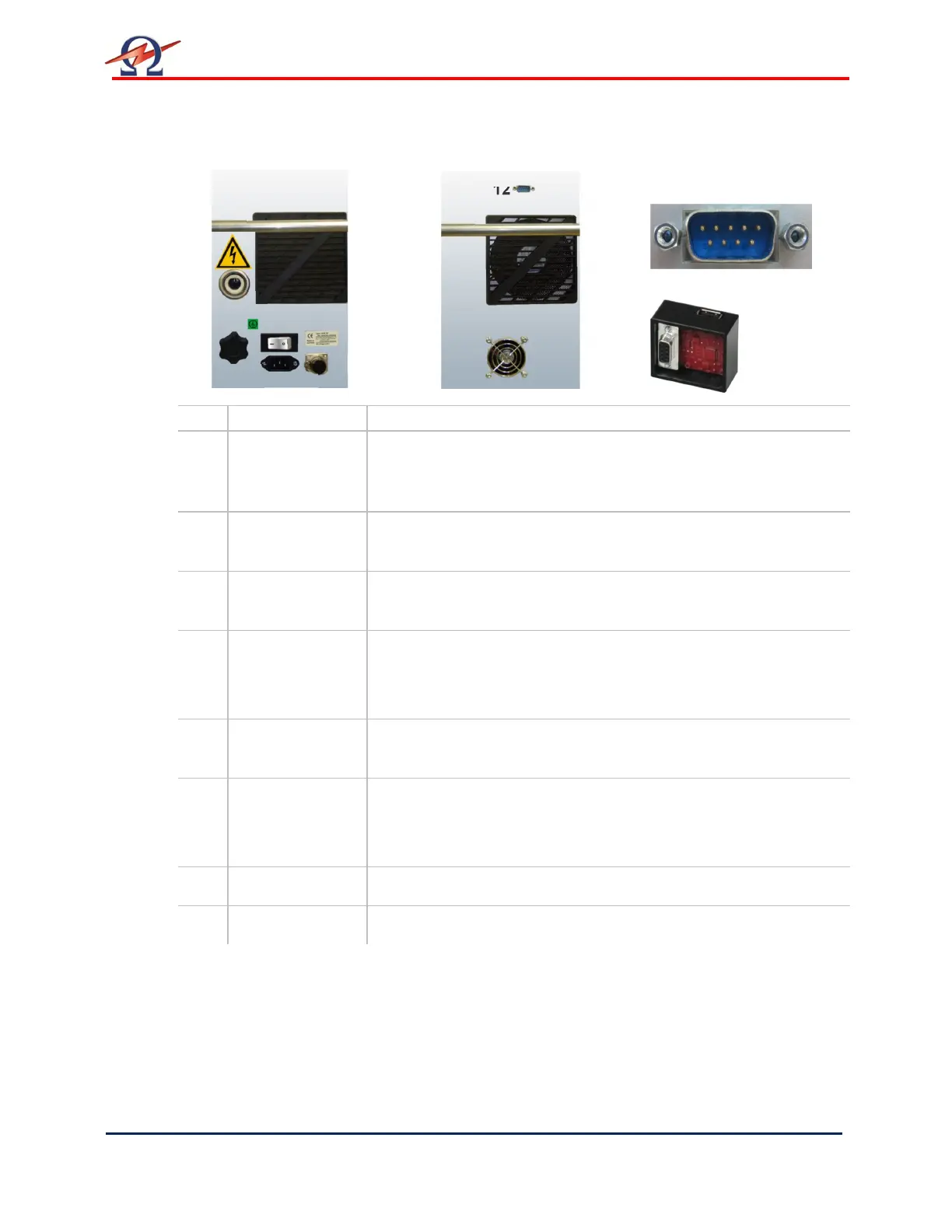
Switches and Controls, continued
Pos.
Name Description
8 Main switch
[on/off]
Activates the HVA.
This switch is a fuse with integrated magnetic auto-reset 10A
• To reset Turn the main switch OFF and then ON again
9 Power supply
plug
Serves as connection point from the HVA to the 110V – 240V,
50/60 Hz power source.
10 Grounding
connector
Serves as connection point from HVA to earth.
11 HV output
connector
Serves as connection point from the HVA to the HV test lead.
To connectScrew the HV test lead into the HV output connector
and tighten
12 Communication
port
Serves as connection point from the HVA to PC (via RS232) or to
a USB device (via USB Flash adapter).
13 Remote control
interlock plug
Provides interlock for the remote switch (i.e. door interlock).
Can be connected to a remote emergency off switch, a gate, foot
pedal or dead man switch
14 Air Vent Air inlet with filter, for cooling of electronic elements.
15 Air Vent Air outlet, for cooling of electronic elements.
Right side Left side Detail Pos. 12
RS232
USB Adapter
11
8
10
12
14 15
9
 Loading...