User Manual
HV Diagnostics Page 24 Rev 9.0
6 Test Procedure
6.1 Equipment Set-up
Steps S1-S9 describe the Equipment Set-up procedure. When carrying
out multiple tests, the ground and power supply connections must
always remain intact. The HV test lead must be reconnected before
each subsequent test (i.e. repeat procedure as of step S3).
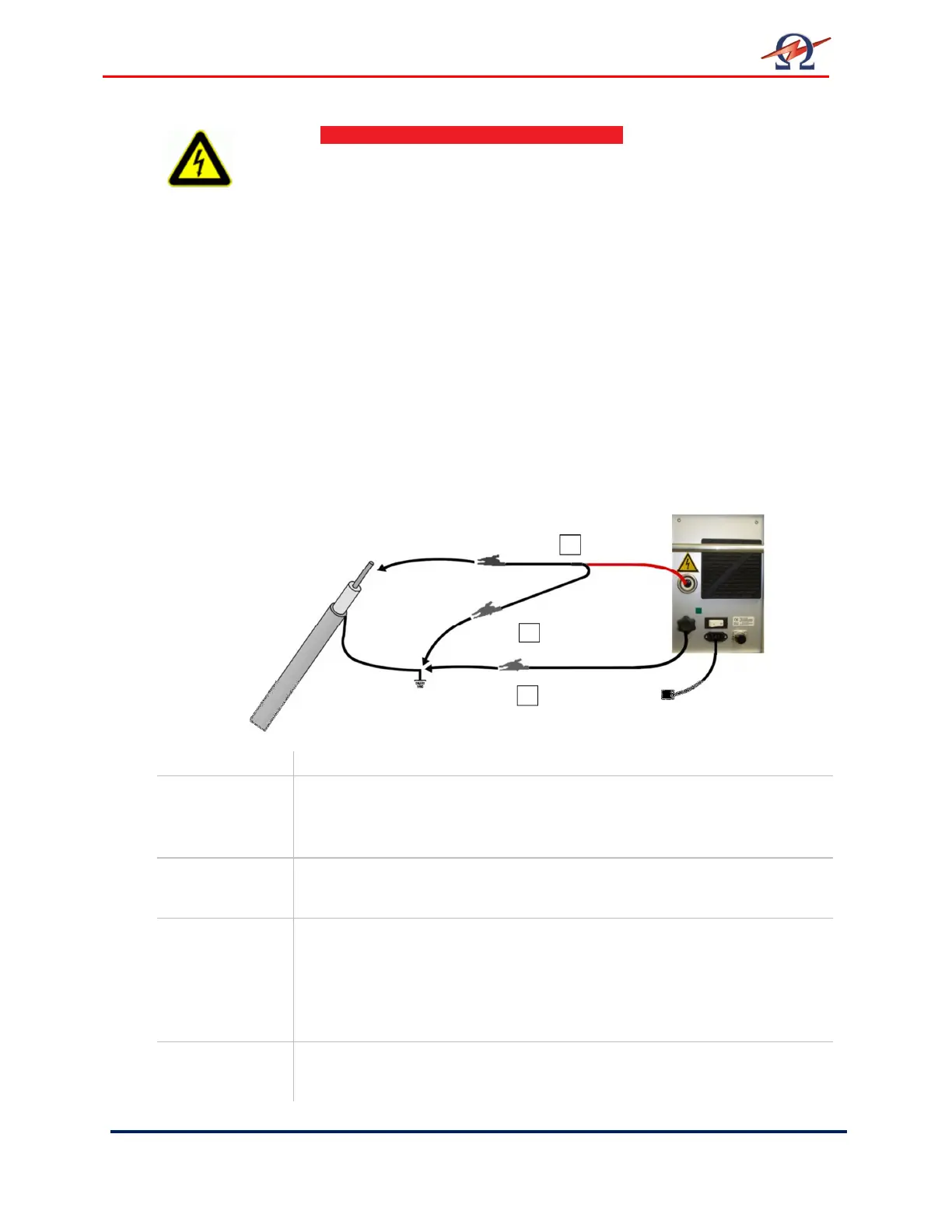
Connection Diagram: Cable Testing
Step Procedure
S1 Connect Grounding Cable
• Connect grounding cable to the HVA grounding connector (10)
• Connect grounding cable to the DUT ground
S2 Connect Power Supply Cable
• Connect the power supply cable to the HVA power supply plug (9)
S3 Connect HV Test Lead
• Screw the HV test lead into the HVA HV output connector (11)
• Connect the HV cable shield to ground.
• Connect other end of HV test lead (clamp including screen protector)
to the DUT.
S4 Verify Connections
• Check that all cables are attached securely.
DANGER
Electric Shock Hazard!
All procedures must comply with local safety regulations.
• Before operating the HVA, equipment set-up procedure must be
completed!
• Cables must be connected in the proper sequence!
• Before turning on the power supply and before activating the HVA,
verify that all system elements are properly grounded!
See 5.1 Equipment Set-up: Steps S 1 –S 7
S1 Grounding
Cable
S3 Test Lead
DUT
S2 Power Supply
 Loading...