User Manual
Rev 9.0 Page 25 HV Diagnostics
Step Procedure
S5 Configure interlock plug (13)
• Verify that the HV Interlock Adapter is connected
If operating with remote controls (Optional):
• Connect external lamps or remote switches
• Refer to 3.3 –Materials, for connection schema and material
requirements
S6
Configure communication port (12)
For USB Data Transfer Mode:
• Connect the USB Flash adapter
Otherwise:
Verify that RS232 cable is NOT connected to the HVA!
S7 Turn “ON” HVA main switch (8)
S8 Turn key switch (7) to the “ON” position
S9
The HVA system automatically boots.
• Start-up default screen appears
”Main Menu” or “Manual Mode” screen
See 4.3 Instrument Set-up
Select appropriate option from default screen and proceed to appropriate
section for further instructions:
• See 5.2 Manual Test Mode or
See 5.3 Automatic Test Mode
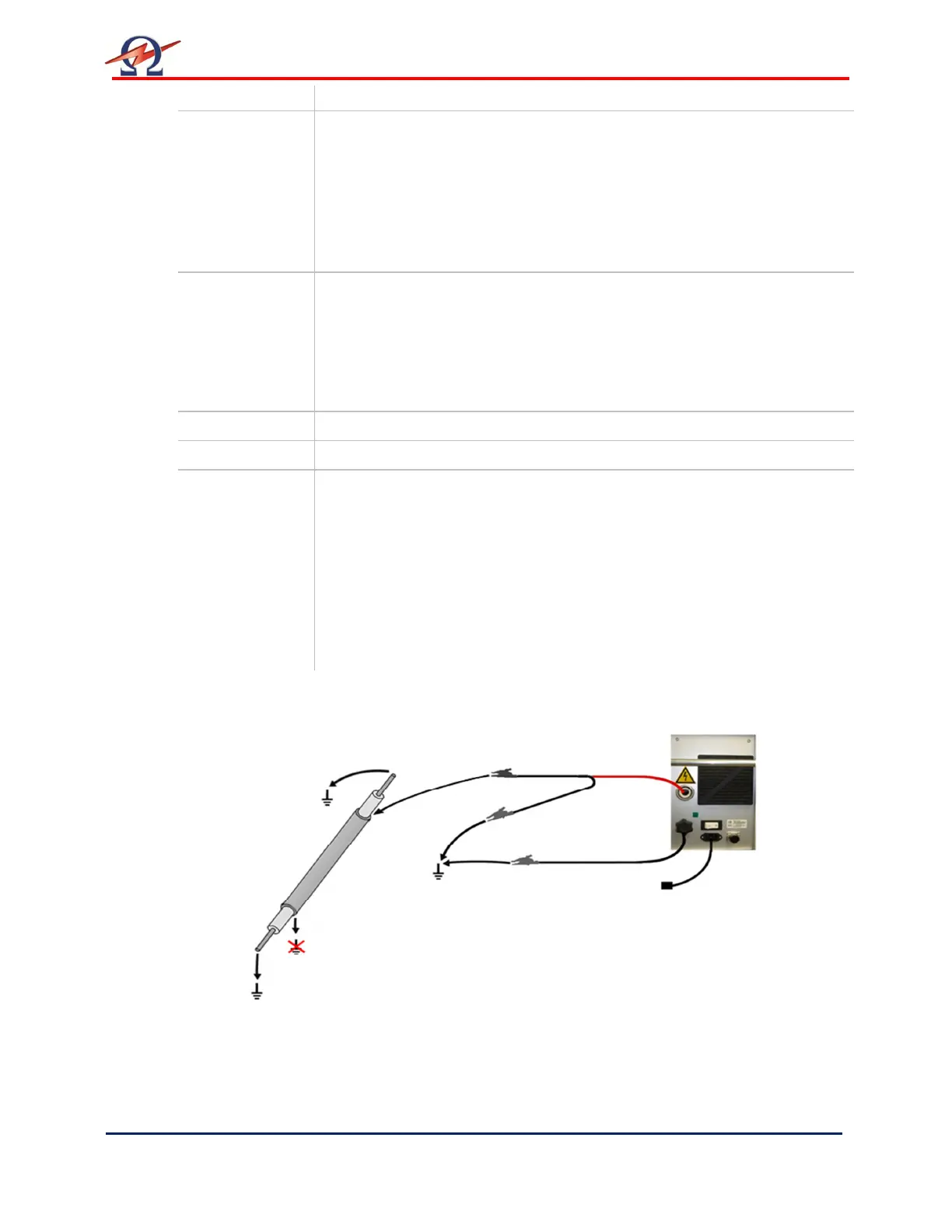
Connection Diagram: Sheath/Jacket Test and Sheath Fault Location
 Loading...