3.2
BLADE CHANGING PROCEDURE
NOTE: Wear gloves for protection from the sharp blade.
1. Open the idler wheel and drive wheel doors and swing the head to
45q as this will make it easier to grip the blade closer to both wheels
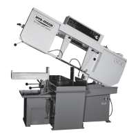
2. Loosen the Blade Tensioner by turning counter clockwise.
3. Loosen the carbide tension handles by turning counter clockwise ¼
turn.
4. At the top of the head, the saw blade runs in a protective channel.
Grip the blade at each end of this channel and twist the blade teeth
down past the channel and slide the blade forward. Let the blade rest
on the out-feed table, and then slide the blade down and out of the
carbide guides.
5. Your new blade will be in a coil. While wearing gloves, hold the blade
away from yourself, and twist the blade to uncoil it. Do not let the
EODGHWHHWKERXQFHRQWKHFRQFUHWHÀRRUDVWKLVPD\FDXVHVRPH
damage.
6. Place the new blade in the carbide guides and then slide the blade
over the wheels. The teeth should be pointing towards the drive side
as they pass through the carbide guides.
7. With the blade in place, turn the tensioner handle clockwise until the large black washer contacts the stop
bolt. This will set the blade tension correctly.
8. With the blade tension set, turn the two carbide-locking handles
clockwise to the locked position. Jog the blade a few rotations to check
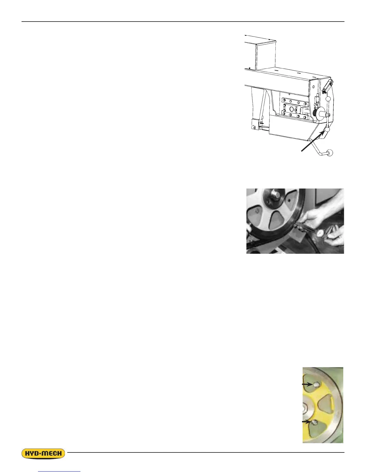
that the blade is not moving in or out on the blade wheels. NOTE: As the
blade tracking will stay fairly constant, it should be checked occasionally
as shown on the drive wheel-tracking photo below. The blade teeth
should protrude from .185” to .200” from the face of the blade wheels. If
the tracking requires adjustment, follow the instruction below.
9. BLADE TRACKING ADJUSTMENT – First, inspect the blade wheels
for wear or damage and repair as required. Blade tracking adjustment
VKRXOGDOZD\VEHJLQDWWKHZKHHOZKHUHWKHWUDFNLQJLVIDUWKHVWRXWRIVSHFL¿FDWLRQ8VLQJWKHLQVWUXFWLRQV
below, adjust the worst wheel, jog the blade and recheck both wheels. Repeat this process until both wheels
DUHZLWKLQVSHFL¿FDWLRQ
a. IDLER WHEEL ADJUSTMENT S-20 Line
On the blade tensioner slide assembly, there are three 9/16” hex head bolts. Loosen the two bolts at the
left end by ¼ turn. Loosen the single bolt at the right side of the slide assembly by ½ turn. In the two holes
above and below this bolt are two 3/16” Allen key set screws. Turn both set screws ¼ turn and tighten the
hex bolt at the right, and then the two bolts at the left. Turning the setscrews clockwise will pull the blade
onto the wheel, and turning counter clockwise will push the blade off the wheel. Each ¼ turn will move the
blade approximately .02” (5.1mm). There is also a single setscrew at the left end of the slider. Turning it
clockwise will push the blade off the wheel.
b. IDLER WHEEL ADJUSTMENT S-23 Line
7KHWUDFNLQJLVDGMXVWHGE\UHJXODWLQJWKH³SXVK´VHWVFUHZVDQGWKH³SXOO´KH[EROWV%HIRUHPDNLQJDQ\
adjustments, bolts A & B should be loosened but remain snug. This will allow easy movement for the slide
assembly. It should be noted that most adjustments can be made with the B & D bolts.
Loosening bolt A and turning in set screws C by equal amounts will move the blade off
the wheel. Loosening bolt B and turning in set screws D by equal amounts will move
the blade on to the wheel. After each C or D adjustment, tighten bolts A & B, run the
blade and then check the tracking.
c. DRIVE WHEEL ADJUSTMENT – On the wall behind the drive wheel are two adjusting
bolt assemblies and two hex bolts. Loosen all four of them with a ¾” socket and turn
the larger hex head bolts ¼ turn with a 1 1/8” socket and extension and then tighten
the two bolts in the assemblies. Then tighten the two hex bolts at the left. Turning the 1
1/8” bolts clockwise will pull the blade onto the wheel and turning counter clockwise will
push the blade off. Each ¼ turn will move the blade approximately .02”.
10. Check the blade brush adjustment (p. 3.4) to be sure the blade is being cleaned properly.
Blade Tensioner