Do you have a question about the Hydac CS 1000 Series and is the answer not in the manual?
Contact details for questions, suggestions, or technical problems.
Information accuracy may change; notify about modifications.
Refers to General Conditions of Sale and Delivery.
Basic prerequisites for safe operation and user responsibilities.
Explains designations and symbols used in the manual.
Explains safety symbols and their meanings.
Defines the intended use of the Contamination Sensor (CS).
Prohibits any use deviating from the designated purpose.
Instructions on checking and maintaining safety devices.
General safety measures and checks for safe operation.
Actions to take in an emergency situation.
Requirements for personnel operating the CS.
Daily checks and operational safety measures.
Safety precautions related to electrical components and work.
Guidelines for maintenance, servicing, and inspection.
Rules regarding modifications to the CS.
Procedures for cleaning and disposing of materials.
How the CS is packed and how to handle it during transit.
Instructions for storing the CS properly.
Specifies temperature and humidity for storage.
Details on identifying the product via its label.
Lists the items included in the CS 1000 package.
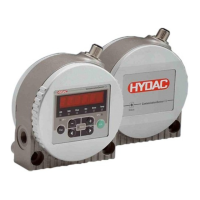
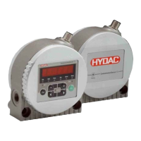
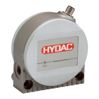
Overview of the CS 1000 Contamination Sensor.
Limitations and qualifications for using the CS with different fluids.
Technical dimensions for models without a display.
Technical dimensions for models with a display.
Describes pipe/hose and flange connection options.
Procedures for unpacking the CS unit.
Methods for physically mounting the CS unit.
How to adjust the CS1000 display orientation.
Steps for connecting the CS to the hydraulic system.
Criteria for selecting an appropriate measurement point.
Graphs showing relationships between flow, pressure, and viscosity.
Step-by-step guide for hydraulic connection.
Diagram illustrating the internal electrical connections.
Details about the electrical connection cable and pin assignments.
Diagrams for connecting the CS to power and a PC.
Describes the continuous measurement mode.
Describes continuous measurement with switching output.
Describes mode for filter control and stopping.
Describes mode for continuous contamination level management.
Describes the single measurement mode.
Explains the front panel display and buttons of the CS122x.
How to lock and unlock the keypad to prevent changes.
Overview of operating modes and their respective menus.
Menu for basic settings upon power-up.
Menu for changing settings during operation.
Details on switching output behavior in different modes.
How the switching output behaves in different modes.
Explains SAE values that can be output via analog.
Correlates current/voltage to SAE classes or errors.
Describes the SAE A-D class output.
Describes SAE A/B/C/D class output.
Explains time-coded signals for SAE classes.
Details the 4-20 mA signal output for SAE classes.
Details the 0-10 V signal output for SAE classes.
Continuous SAE class output.
SAE+T signal with time-coded values.
Time-coded signal for SAE+T.
4-20 mA signal for SAE+T.
0-10 V signal for SAE+T.
Overview of ISO output values.
Correlates current/voltage to ISO classes or errors.
Continuous ISO class output.
Time-coded 3-digit ISO code signal.
4-20 mA signal for ISO Code.
0-10 V signal for ISO Code.
ISO+T signal with time-coded values.
4-20 mA signal for ISO+T.
0-10 V signal for ISO+T.
Relationship between fluid temperature and output signal.
Table correlating temperature to current/voltage.
Details on the RS-485 serial interface.
Lists items included with the CSI-D-5.
Diagram showing how to connect the CSI-D-5.
Instructions for setting up the power adaptor.
Information about the CoCoS 1000 PC software.
Hardware and software requirements for CoCoS 1000.
Steps to install the driver for the adaptor box.
Step-by-step guide to install the CoCoS 1000 software.
Instructions for launching and using CoCoS 1000.
How to save measurement data to a file on the PC.
Addresses issues like missing CS font during installation.
Step-by-step instructions for removing the CS.
Guidelines for proper disposal and decommissioning.
Lists available spare parts and accessories.
Explains the ISO 4406:1999 standard for particle counts.
Table allocating particle counts to cleanliness classes.
Explains SAE AS 4059 standard for cleanliness classes.
Table showing cleanliness in relation to particle concentration.
Explains the LED status indicators and error codes.
Lists the factory default settings for the Power Up menu.
Lists the factory default settings for the Measuring menu.
General specifications like mounting, display, and IP class.
Hydraulic specifications like pressure, flow rate, and viscosity.
Electrical specifications like voltage, power, and interfaces.
Information on shipping address for recalibration and repair.
Explains the model code structure and options.
| Brand | Hydac |
|---|---|
| Model | CS 1000 Series |
| Category | Accessories |
| Language | English |