Do you have a question about the Hydac CS1000 series and is the answer not in the manual?
Contacting HYDAC for product questions and required information.
Reference to HYDAC FILTER SYSTEMS GMBH delivery terms for warranty.
Guidance on locating specific information within the manual using TOC.
Explanation of symbols indicating hazards to persons, property, or environment.
Definitions of DANGER, WARNING, CAUTION, and NOTICE signal words.
Details hazards and damage risks associated with non-intended sensor operation.
Specifies requirements for personnel operating or working with the sensor.
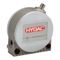
Explains how to identify product details from the model code label.
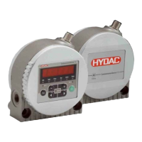
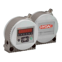
Technical drawings showing physical dimensions for the CS1x1x model.
Technical drawings showing physical dimensions for the CS1x2x model.
Overview of available connection types for the sensor.
Guidelines for choosing an optimal installation point for accurate readings.
Step-by-step instructions for connecting the sensor to the hydraulic system.
Details the function of each pin in the sensor's connector.
Explains the wiring color codes for the sensor's connection cable.
Describes Mode M1 for standalone sensor operation with display and analog output.
Details Mode M2 for continuous monitoring with alarm and switching outputs.
Explains Mode M3 for controlling a filter unit based on cleanliness levels.
Describes Mode M4 for automated control of filtration units based on limits.
Explains Mode "SINGLE" for performing a single, standalone measurement.
Explains the purpose and operation of each button on the sensor's keypad.
Shows how ISO, SAE, and NAS cleanliness classes are displayed.
Explains how flow rate, analog output, drive, and temperature are displayed.
Instructions for locking and unlocking the sensor's keypad to prevent accidental changes.
Visual representation of the menu hierarchy for CS 12xx models.
Visual representation of the menu hierarchy for CS 13xx models.
Explains the purpose and function of the switching output in Mode M1.
Describes the switching output behavior in Mode M2 for control applications.
Details switching output function in Mode M3 for pump control.
Explains switching output usage in Mode M4 for maintaining cleanliness limits.
Details the 4-20 mA and 2-10 V analog output types based on model code.
Explains how SAE classes are read via analog output and provides current/voltage mappings.
Explains ISO values read via analog output and provides current/voltage mappings.
Explains NAS values for CS 13xx and provides current/voltage mappings.
Explains current/voltage ranges based on fluid temperature and provides conversion formulas.
Details the meaning of LED status codes and display messages for normal operation.
Lists error codes, their meanings, remedies, and associated error numbers.
Details error conditions like no display, firmware error, and communication error.
Explains how measured value signals are output during error states with examples.
Recommends sensor recalibration every 2-3 years by HYDAC-certified service.
Step-by-step guide for safely disconnecting and removing the sensor.
Summarizes mounting position, self-diagnostics, display, measured variables, and accuracy.
Covers operating pressure, connection types, flow rate, and viscosity range.
Details connection plug, power supply, power consumption, and analog/switching outputs.
Lists default settings for PowerUp and Measuring menus.
Explains the structure and meaning of the CS1000 model code for configuration.
Introduces ISO 4406:1999 cleanliness standards and particle count assignments.
Explains SAE AS 4059 cleanliness standards and provides particle count tables.
Explains NAS 1638 cleanliness standards and provides particle concentration tables.
Provides definitions for terms like Single measurement, Measuring point, and Measurement duration.
Lists and defines common abbreviations and terms used in the manual.
| Series | CS1000 |
|---|---|
| Category | Accessories |
| Measuring principle | Light extinction |
| Housing material | Stainless steel |
| Protection class | IP65 |
| Application | Offline oil analysis, condition monitoring of oils |
| Fluid compatibility | Mineral oils, synthetic oils |
| Particle size range | 4 µm (c), 6 µm (c), 14 µm (c), 21 µm (c) |
| Measuring ranges | ISO 4406, NAS 1638, SAE AS4059 |
| Storage temperature | -20 to +70 °C |
| Power supply | 24 V DC |
| Interfaces | RS-232 |
| Electrical connection | M12 connector |
| Operating temperature range | 0…100 °C |