6 INSTALLATION AND START-UP
6.1 Warning:
– Do not insert or remove the driver while the electronic system is energized
– Connect the electronic driver according to the desired connection scheme (see
,
)
– The voltages must be always measured in reference to the GND (pin 8a of the connector)
– Refer to to identify the components mentioned in the setting procedure
– To check the reference signal and the regulated valve opening , use the test points T1 and T2
the on front panel.
– To check the correct solenoid command for positive and negative regulations, use the two led
S1 and S2 (only for drivers E-ME-T-05H)
6.2 Start-up
It is possible that the factory settings do not match the required performances for the specific
application. The system can be optimized on field, by setting in sequence the bias, scale and
ramp potentiometers.
It is advisable to perform calibration procedures in the order given below.
Bias adjustment (dead band compensation), see
, , .
–
Supply a reference signal voltage (0 V
DC
for E-ME-T-01H and ±0,2 V
DC
for E-ME-T-05H;
– Gradually turn potentiometer(s) (P1 for coil S1 and P2 for coil S2) until a movement of the control-
led actuator is obtained.
– Turn slowly in the opposite sense until stop is obtained.
Scale adjustment, see
, ,
Set the switch A (see…..) depending to the selected range of the reference signal.
In case it is required the regulation of the valve max opening, proceed as follow:
– supply max reference signal (for E-ME-T-05H driver repeat for max negative voltage) in the
specificated range and turn counterclockwise internal scale potentiometers P5 and P6 (factory
preset to 100%) to reduce valve opening (see -C).
Gain see
,
(only for adjustment TH* and TK*).
Front panel potentiometer P7 could be rotated to increase sensitivity and positioning accuracy of
the axis (clockwise rotation = increase in sensitivity). Factory preset completely counterclockwise).
Ramps (see
,
).
If the card is being used in a open loop system push the switch from position ramp off (standard)
to position ramp on, (see -B). Calibrate the ramp settings only if dynamic impacts and tenden-
cies towards instability persist after optimizations of the whole system. Adjust the ramp settings
using the ramp potentiometers (P3 and P4) until the phenomenon has been eliminated (Clockwise
rotation = increase in ramp time).
8
1211
7
7
87
98
1097
1098
G140
9 E-ME-T-01H DIAGRAM
10 E-ME-T-05H DIAGRAM
Reference [V]
Valve opening [%]
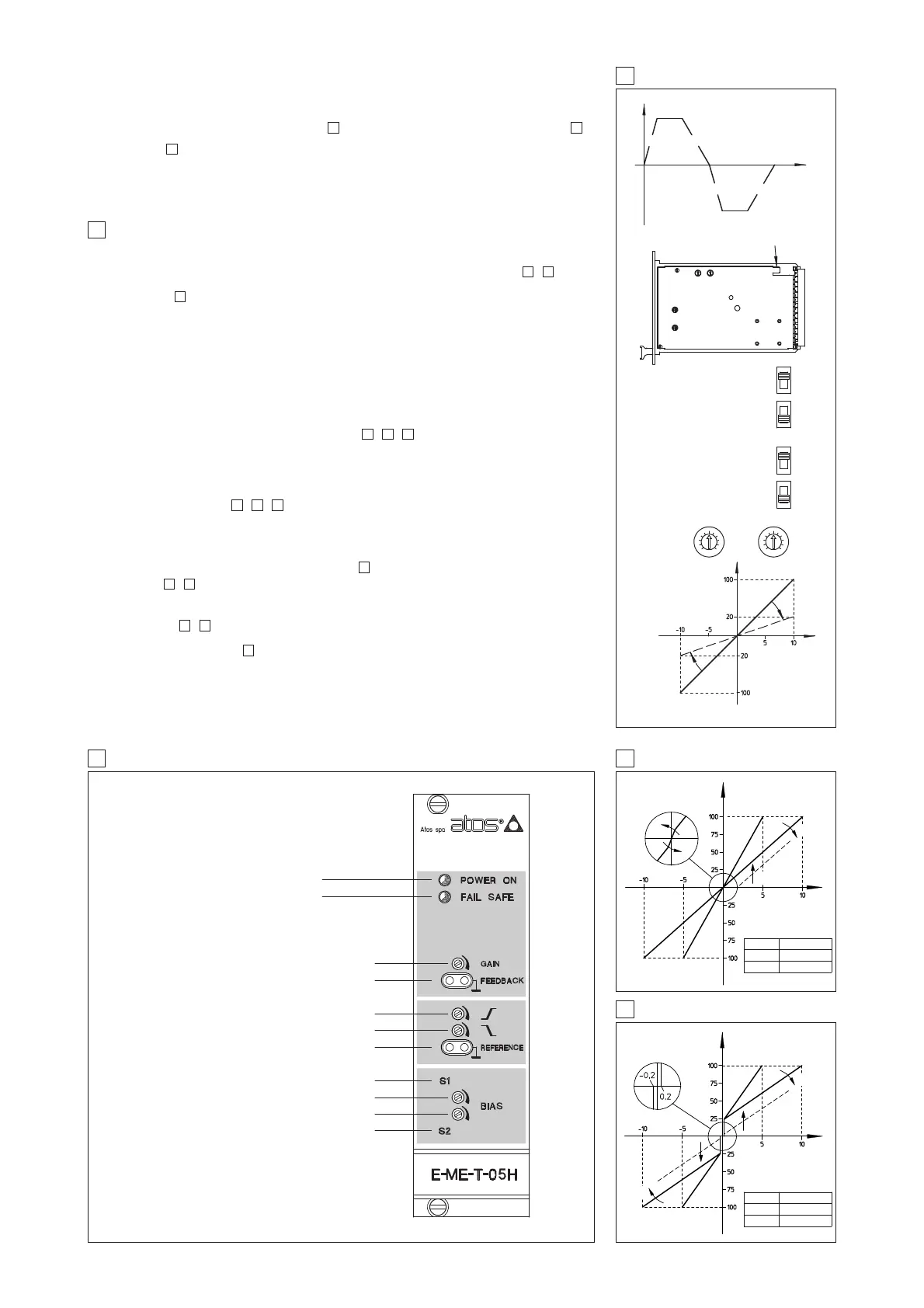
7 RAMPS AND SETTINGS
DISSYMETRICAL RISIND AND
FALLING RAMPS GENERATOR
P3 P4
P3 P4
A
B
POS. 1 = 0 ÷ +10 / ±10 V
(STD SETTING)
POS. 2 = 0 ÷ +5 / ±5 V
RAMP OFF
(STD SETTING)
RAMP ON
P5 P6
SCALE
SWITCH
RAMP
SWITCH
Reference [V]
Valve opening [
%]
Valve Opening
C
ATTENUATION
TILL 20% OF FULL
REFERENCE
SIGNAL
Time
A
B
C
CONNECT TO AN EFFICIENT EARTH POINT
8 E-ME-T-05H TOPOGRAPHICAL VIEW OF REGULATIONS
Power on (green)
Fail safe led (red)
Channel enabled led (solenoid S1) S1
Rising ramp P3
Falling ramp P4
Reference signal test point T1
Bias solenoid S1 P1
Bias solenoid S2 P2
Channel enabled led (solenoid S2) S2
Transducer position test T2
Gain regulation ± 0,4% P7
1)
2)
1)
1)
1) Only for E-ME-T-05H/*
2) Only for E-ME-T-01H/* /TH* and /TK*
P7
Reference [V]
Valve opening [%]
The two available regulations P3 and P4 permit to respectively regulate the ramp times for positive
and negative variations of the reference signal. In case of application of the driver in closed loop
systems, it is advisable to disable the ramp function: it is possible to permanently disable this func-
tion by means of a switch on the card side ( ) or temporarily, connecting the pin 6c and 6a ( )
Gain, see (only for adjustments TH* and TK*).
Pressure gain adjustment around “zero” increases sensitivity and positioning accuracy of the axis
and optimize the valve operation according to the stiffness of the system by increasing the hydrau-
lic gain of the valve around the hydraulic zero.
127
8
SWITCH A
REFERENCE [V]
POS. 1 ±10
POS. 2 ± 5
P1
P2
SWITCH A
REFERENCE [V]
POS. 1 0 ÷ 10 (±10)
POS. 2 0 ÷ 5 (± 5)
P1
P5
P6
P5
P6
P5