Power supply
(positive at contacts 2a, 2c)
(negative at contacts 4a, 4c)
Max power consumption 50 W
Current supplied to solenoid Imax= 3.3A square wave PWM type
Nominal reference signal, factory preset E-ME-L-01H : 0 ÷ 10 V at contact 12c (GND on 16ac) (± 10 V option see 4.2)
for /I option : 4 ÷20 mA at contact 12c (+) and 8a (-)
Reference signal variation range, ± 10 V (SW pos. 1) and ± 5V (SW pos.2)
(internal scale adjust option) 0 ÷ 10 V (0 ÷ 5 V) for valves with one external position (DPZO-L-*5, LIQZO-L-**2)
Input signal impedence Voltage Ri > 50 KOhm - (/I option Ri = 316 Ohm)
Potentiometers supply +10 V / 10 mA at contact 10c and -10 V / 10 mA at contact 14c
Ramp time 14 sec. max (0 ÷100% of reference signal)
Enabling signal V = 5 ÷24 V
DC
on contact 8c with led indicator on panel; Ri ³ 30 kw (max 3 mA)
Electrical wiring Coil : 2 x 1,50 mm
2
to 20 m 2 x 1,5 mm
2
shielded to 40 m
Transducer : 4 x 0,25 mm
2
to 20 m 4 x 0,5 mm
2
shielded to 40 m
Card format Europe 100x160 mm (Plug in unit DIN 41494)
Card connector Male DIN 41612 /D
Connector elements available Type E-K-32M frame snap connector (see table G800) to be ordered separately
Operating temperature 0 ÷ 50 °C (storage -20 ÷ +70 °C)
Front panel dimensions 128,4 x 35,3 mm
Weight 520 gr.
Features Position control by PID action - Rapid solenoid excitation and switching off - Outputs to solenoids pro-
tected against accidental short circuits - Feedback cable break produces an inhibit of the driver,
zeroing the current and creating a fail-safe position in the valve.
Nominal : 24 V
DC
Rectified & filtered : V
RMS
= 21÷33 (max ripple = 2Vpp)
3 MAIN CHARACTERISTICS OF E-ME-L ELECTRONIC DRIVERS
4 GENERAL SPECIFICATIONS
4.1 Power sup ply and wir ings
The power sup ply must be appro pri ate ly sta bi lized or rec ti fied and fil tered. If the power sup ply is
gen er at ed by a single phase rec ti fi er, use a 10000µF/40V capac i tor; if pulse volt age is gen er at ed
by a three phase rec ti fi er con nect a 4700µF/40V capac i tor (see ).
Connect the reference signal to the main electronic control by means of shielded and twisted
cables. Pay attention: the negative and the positive poles must not be exchanged each other.
Shield the wirings to avoid electromagnetic noise (EMC).
It is suitable to keep the driver and its cables far from any electromagnetic radiation source (like
cables where high currents flow, electric motors, transformers, relays, solenoids, portable radio-
transmitter, etc.).
Wire the earth connection as shown in , according to CEI EN 60204-1 standards.
Connect the shield of the driver to the noiseless earth terminal (TE) .
4.2 Reference sig nal
The elec tron ic driv er is designed to receive exter nal volt age or cur rent ref er ence sig nals accord -
ing to .
Note that driv ers suit able to receive cur rent ref er ence ( option /I) have sig nal val ues in the range 4
to 20mA. For single solenoid valves with two external positions (*60), the reference signal is sym-
metrical ±10 V (±5 V).
4.3 Enabling signal
The digital signal on contact 8c allows to enable (24 V
DC) or disable (0 V) the driver without swit-
ching off the power supply; use this signal to cyclically inhibit the driver or in emergency conditions
4.4 Set code
Basic cal i bra tion of the elec tron ic driv er is fac to ry pre set accord ing to pro por tion al valve it has to be
cou pled with. These pre-cal i bra tions are iden ti fied by a stan dard num ber in the model code as fol low:
(*) These codes have the main stage tranducer connection different from standard (see
,
-
connection type B)
For ex-proof valves, insert an "A" in the fifth digit of the code adjustment; for example, the code
adjustment for DPZA-L-15* is DL15AA (see table E120).
4.5 Calibrations/set tings available to the user, see
, , , .
Scale, see
The Scale regulation, available on the card side, permits to modify the relation between the refe-
rence signal and the position or the regulated flow.
Modifying this regulation it is possible to fit the valve hydraulic behaviour to the effective system
conditions; in addition the two regulations available for pos i tive and neg a tive ref er ence sig nals
permit to set different hydraulic adjustments for positive and negative movements.
The Scale regulation is factory set in order to control the max valve opening with 100% of the refe-
rence signal (10 V).
1211
7
13
11
10987
5
11
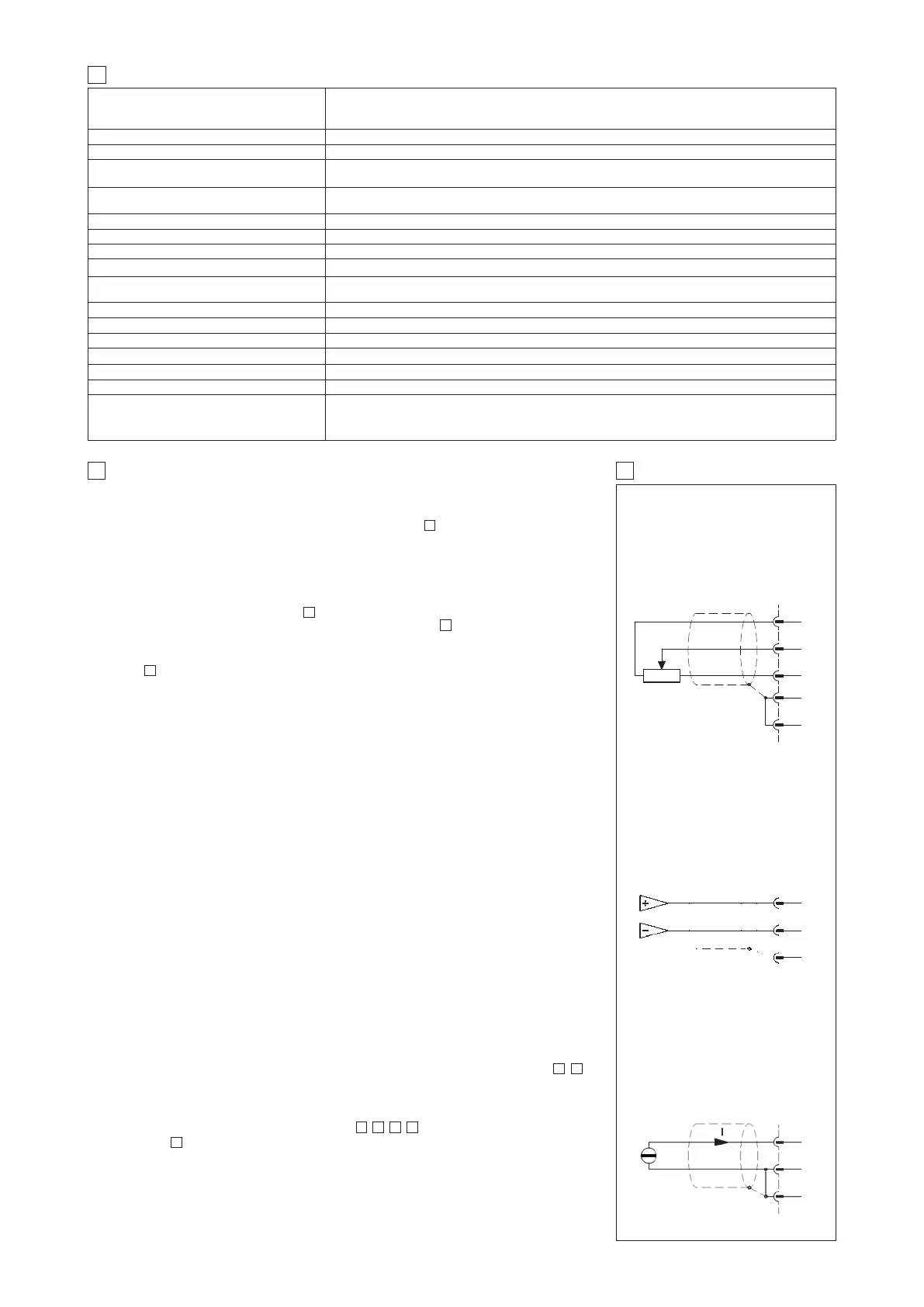
5 EXTERNAL REFERENCE SIGNALS
10c
12c
14c
16c
8a
EXTERNAL
POTENTIOMETER
±10 V REFERENCE
10 Kw
CONNECTIONS
12c
8a
16c
DIFFERENTIAL
EXTERNAL REFERENCE
/I OPTION 4 ÷ 20 mA
12c
8a
16c
DPZO-L-370*/B = DL36SB
DPZO-L-37* = DL37SB
DPZO-L-37*/B = DL37SB
DPZO-L-65* = DL65SA
DPZO-L-660/670 = DL66SA
DPZO-L-67 = DL67SA
LIQZO-L-162L4 = LQ12SA
LIQZO-L-252L4 = LQ22SB
LIQZO-L-253L4 = LQ23SB
LIQZO-L-322L4 = LQ32SA
LIQZO-L-323L4 = LQ33SA
LIQZO-L-402L4 = LQ42SB
LIQZO-L-403L4 = LQ43SA
LIQZO-L-502L4 = LQ52SB (*)
LIQZO-L-503L4 = LQ53SB (*)
LIQZO-L-632L4 = LQ62SC (*)
LIQZO-L-633L4 = LQ63SC (*)
LIQZO-L-802L4 = LQ82SC (*)
LIQZO-L-803L4 = LQ83SD (*)
LIQZO-L-10002 = LQ92SC (*)
DPZO-L-15* = DL15SA
DPZO-L-15*/B = DL15SA
DPZO-L-160/170 = DL16SA
DPZO-L-17* = DL17SA
DPZO-L-17*/B = DL17SA
DPZO-L-25* = DL25SB
DPZO-L-25*/B = DL25SB
DPZO-L-260* = DL26SB
DPZO-L-270* = DL26SB
DPZO-L-260*/B = DL26SB
DPZO-L-270*/B = DL26SB
DPZO-L-27* = DL27SB
DPZO-L-27*/B = DL27SB
DPZO-L-35* = DL35SB
DPZO-L-35*/B = DL35SB
DPZO-L-360* = DL36SB
DPZO-L-370* = DL36SB
DPZO-L-360*/B = DL36SB