G150
6 INSTALLATION AND START-UP
6.1 Warning
– Do not insert or remove the driver while the electronic system is energized.
– Connect the electronic driver according to the desired connection diagram
(see
,
)
– The voltages must be always measured in reference to the GND (pin 16a of the connector).
– Refer to to identify components mentioned in the setting procedure.
– To check the reference signal and the regulated valve opening , use the test points T1 and T2
the on front panel.
6.2 Start-up
Factory preset adjustments may not meet the desired requirements for the specific application and
performances can be optimized by on-site re-adjustements of bias, scale and ramps potentiome-
ters, in sequence. It is advisable to perform calibration procedures in the order given below.
Bias adjustment (dead band compensation), see
, , .
– Supply a reference signal voltage = 0V
DC
.
– Gradually turn bias potentiometer P1 until a movement of the controlled actuator is obtained.
– Turn slowly in the opposite sense, until stop is obtained.
Scale adjustment see
, , .
Factory preset reference signal is ± 10V (selector in positon 1). If a 0 ÷ 5V (± 5V) reference signal
is available, set selector in position 2 ( see -A).
– Only in particular cases when a non standard reference signal is available it is possible to
adjust maximum valve opening with scale regulation proceeding as follow :
– supply max reference signal voltage (repeat for max negative voltage) in the specificated
range and turn counterclockwise internal scale potentiometers P5 and P6 (factory preset to
100%) to reduce valve opening (see -C).
Ramps (see
,
)
If the card is being used in a open loop system push the switch from position ramp off (standard)
to ramp on, (see -B). Calibrate the ramp settings only if dynamic impacts and tendencies
towards instability persist after optimizations of the whole system. Adjust the ramp settings using
the ramp potentiometers (P3 and P4) until the phenomenon has been eliminated (Clockwise rota-
tion = increase in ramp time).
1110
7
87
7
7
1097
1098
8
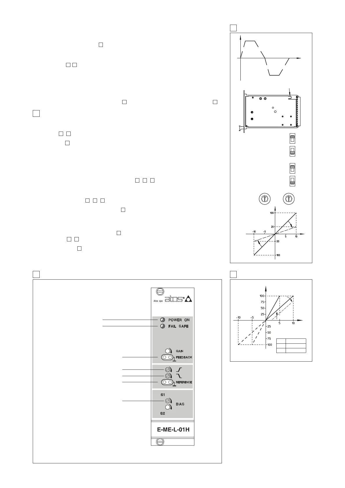
8 E-ME-L-01H TOPOGRAPHICAL VIEW OF REGULATIONS
7 RAMPS AND SETTINGS
9 E-ME-L-01H DIAGRAM
DISSYMMETRICAL RISING
AND FALLING RAMPS
GENERATOR
P3 P4
P3 P4
A
B
C
SCALE
SWITCH
RAMP
SWITCH
POS. 2 = 0 ÷ +5 / ±5 V
POS.1 = 0 ÷ +10 / ±10V
(STD SETTING)
RAMP ON
RAMP OFF
(STD SETTING)
Power on led (green)
Fail safe led (red)
Falling ramp P4
Reference signal test point T1
Bias solenoid P1
Reference [V]
Valve Opening [%]
Rising ramp P3
Main spool position test point T2
Valve Opening
Time
Valve opening [%]
P6
P5
Reference [V]
ATTENUATION TILL
20% OF FULL
REFERENCE SIGNAL
CONNECT TO AN EFFICIENT EARTH POINT
A
B
C
B
A
C
P5
P6
SW REFERENCE
POS. 1 ÷ 10 (± 10) std.
POS. 2 0 ÷ 5 (± 5)
Bias (dead band compensation)
The bias regulations, available on the front panel (P1), permit to set the correspondence between
the electrical zero of the reference signal with the beginning of the valve’s hydraulic regulation,
compensating the dead band and the component’s mechanical tolerances .
Modifying this regulation (see ) it is possible to fit the valve hydraulic behaviour to the effective
system conditions.
This regulation is factory set at the standard values depending to the proportional valve to be con-
trolled and it is identified by the driver set code (see 4.4)
Ramps, see
, .
The ramp regulation, available on the front panel, permit to modify the time in which the valve rea-
ches the set opening value in front of a step change of the reference signal.
The ramp regulation is factory set at value close to zero and it can be increased up to 14 sec max
for a step change of the reference signal from 0% to 100%.
The two available regulations P3 and P4 permit to respectively regulate the ramp times for positive
and negative variations of the reference signal. In case of application of the driver in closed loop
systems, it is advisable to disable the ramp function: it is possible to permanently disable this func-
tion by means of a switch on the card side ( ) or temporarily, connecting the pin 6c and 6a ( )
9
127
117
P5
P1