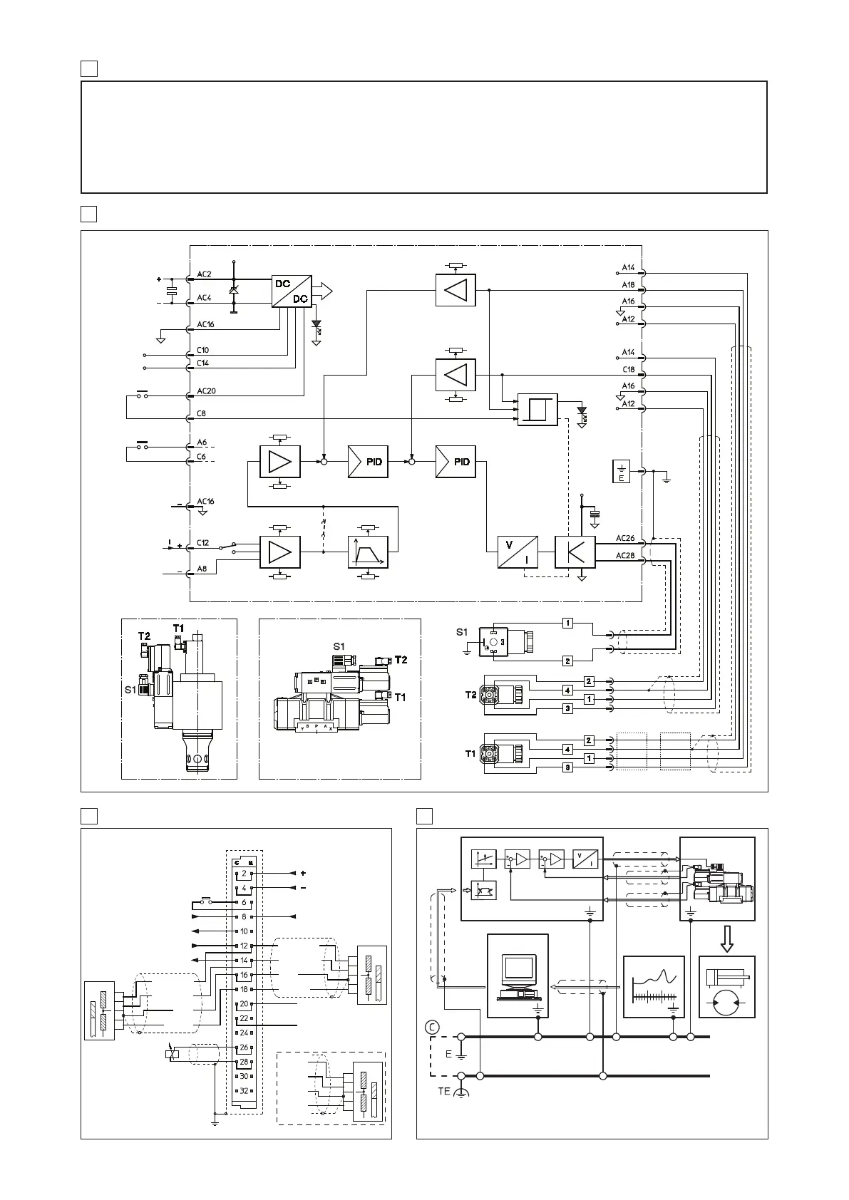
11 WIRING BLOCK DIAGRAM
07/12
12 GENERAL CONNECTIONS
E-ME-L-01H
ENABLE
+10 V
DC 10 mA
REFERENCE +
-10 V
DC 10 mA
-15 V
DC 20 mA
+15 V
DC 20 mA
GND
IN E-TH-*
-15 V
DC 20 mA
+15 V
DC 20 mA
GND
IN E-TH-*
COIL S1
MAIN STAGE
24 V
DC
AXIS READY
24 V
DC
2
3
4
1
PILOT STAGE
RAMP EXCLUSION
REFERENCE -
POWER SUPPLY
24 V
DC ± 10%
POWER GND
SIGNAL GND
DIFFERENTIAL
INPUT
REFERENCE
REFERENCE GND
WITH COMMON
GROUND
RAMP
SWITCH
+24 V
ENABLE
+10 V
-10 V
x 1 (
*)
x 0,5
+VCC
TRANZORB
INTERNAL
SUPPLY
GREEN
LED
SCALE
SWITCH
RAMP
SWITCH OFF
DEAD BAND S2
RAMP 1
P5
FEEDBACK FEEDBACK
SCALE
SCALE
OFFSET
REFERENCE
CURRENT
FEEDBACK
MAIN STAGE FEEDBACK
PILOT FEEDBACK
-15 V
RED
LED
SHIELD
+VCC
-15V
GND
SIGNAL
+15V
SHIELD
SHIELD
(
*)
(
*) = FACTORY PRESET
DIRECT PILOTED VALVEEXTERNAL PILOTED VALVE
ELETTROMAGNETIC COMPATIBILITY
Atos electronic drivers and proportional valves are designed according to the 2004/108/CE Directive (Electromagnetic Compatibility) and according to
EN 50081-2 (Emission) and EN 50082-2 (Immunity) standards. The electromagnetic compatibility of electronic drivers is valid only for wirings realized
according to the typical electric connections shown in this technical table.
The device must be verified on the machine because the magnetic field may be different from the test conditions.
SAFETY
The electrical signals (for example reference signals, feedback and enable signal) of electronic drivers must not be used to realize safety condi-
tions of the machine. This is in accordance with the provisions of european directives (Safety requirements of fluid technology systems and com-
ponents-hydraulics, EN 982). Special attention must be payed to switch-on/switch-off of electronic drivers because they could produce uncontrol-
led movements of actuators operated by the proportional valves.
10 IMPORTANT INSTRUCTIONS
13 EARTH CONNECTIONS
CONTROL UNIT
E-ME-L-01H
PROPORTIONAL VALVE
DRIVING CURRENT
TRANSDUCER ACTUATORS
RAMPS
BIAS
CURRENT
AMPLIFIER
PILOT STAGE
E: PROTECTIVE EARTH TE: NOISELESS EARTH
C : ALTERNATE BONDING CONNECTION TO NOISELESS EARTH TERMINAL
DEAD BAND S1
P6
RAMP 2
+15 V
-15 V
+15 V
MAIN STAGE
CONNECTOR TYPE SP-666 (see K500 table)
CONNECTORS TYPE SP-345 (see K500 table)
COIL S1
N.C.
+24 V
DC
GND
SIGNAL
Standard
connection
Connection type B, see § 4.4
-15 V
GND
SIGNAL
+15 V
N.C.
GND
SIGNAL
+24 V
Standard
connection
Connection type B (see § 4.4)
 Loading...