Options, see section
4
- = standard version (with 5 m cable)
I = current reference input
M12 = with 5 poles M12 connector (*)
W = power limitation function (see 6.7)
Digital electronic drivers type E-MI-AS-IR
DIN 43650 plug-in format, for proportional valves without transducer
Table G020-7/E
E-MI-AS digital drivers are designed for
mounting on the solenoid’s DIN connector
of proportional valves without transducer.
They supply and control the current to the
solenoid according to the electronic refe-
rence input signal. The solenoid propor-
tionally transforms the current into a force,
acting on the valve spool or poppet,
against a reacting spring, thus providing
the valve’s hydraulic regulation.
E-MI-AS drivers can drive single or dou-
ble solenoid proportional valve.
Electrical Features:
• Standard 5m cable connection or
M12 connector (/M12 option)
• Infrared communication interface to
program the driver with Atos PC
software
• 2 leds for diagnostics: driver status
and solenoid status
• +5
VDC output supply for external refe-
rence potentiometer (not available for
/M12 option)
• Current reference input (/I option)
• Plastic box with IP65 protection degree
and standard DIN43650 plug-in format
with double earth connection to allow
double-side orientation
• CE mark according to EMC directive
Software Features:
• Setting of valve’s functional parame-
ters: bias, scale, ramps, dither
• Linearization function for the hydraulic
regulation
• 2 selectable modes for electronic refe-
rence signal: external analog input or
internal generation
• Max power limitation (/W option)
• Selectable range of electronic referen-
ce analog input: voltage or current
(/I option)
• Complete diagnostics of driver status,
solenoid and driver fault conditions
• Intuitive graphic interface
E - MI -
A S
- 01H /* **
Electronic driver in plug-in
format DIN 43650
1 MODEL CODE
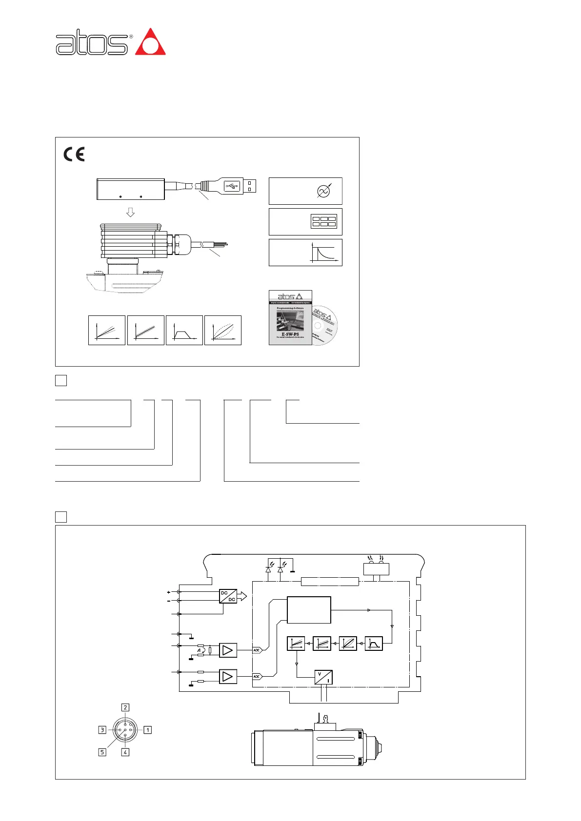
2 BLOCK DIAGRAM
Series number
G020
www.atos.com
01H = for single solenoid proportional valves
A = driver for valves without
transducer
-
IR = Serial infrared communication interface
DC/DC
CONVERTER
RAMPSBIAS
SCALE
MICROCONTROLLER
INFRARED
INTERFACE
DRIVER STATUS
SOLENOID
LINEARIZATION
REFERENCE
CURRENT TO
SOLENOID
infrared interface E-A-PS-USB/IR
S = digital execution
E-SW-PS
programming software
Bias Ramps Linearization
Enhanced
Diagnostic
Internal
Reference
Generator
Scale
proportional solenoid
(*) Note: ZH-5P female connector must be ordered separately.
POWER SUPPLY V+
POWER GND
OUTPUT SUPPLY (*)
AGND (SIGNAL ZERO)
CMD 1
CMD 2
RX
TX
REFERENCE
GENERATOR
LOGIC
(*) +5 V
DC / 5 mA output supply for external potentiometer not available for /M12 option
Hydraulic
Power
Limitation
(option /W)
IR
E-MI-AS-IR-01H
LEDS :
5 PIN CONNECTOR
/M12 option
(driver side)