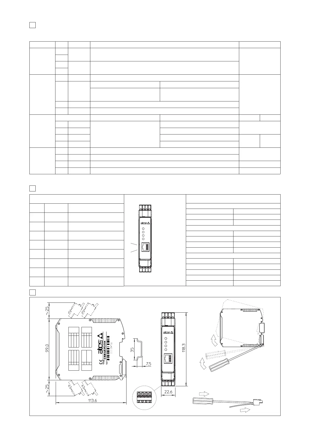
9 DIMENSIONS [mm] AND INSTALLATION
07/13
1
2
1
1 2 3 4
2
To wire cables in the connectors:
1 - press the button with a screwdriver
2 - insert the cable termination
To unlock the driver from the DIN rail:
1 - pull down the locking slide with a
screwdriver
2 - rotate up the driver
7 DRIVER CONNECTIONS
CONNECTOR PIN SIGNAL TECHNICAL SPECIFICATIONS NOTES
A
A1
SOL S1 Current to solenoid S1
Output - power PWM
A2
A3
SOL S2 (*)
Current to solenoid S2
A4
B
B1
CMD1 Reference analog input: ±10 VDC / ± 20 mA maximum range software selectable (see 4.2)
Input - analog signal
B2
CMD-
Standard
/P option (see 4.4)
Zero signal, ground for reference signals Reference for ±5 VDC output (AGND)
B3
CMD2 (*)
Reference analog input: ±10 VDC / ± 20 mA maximum range software selectable (see 4.2)
B4
DGND Optical insulated ground for on/off inputs (DI1 ÷ DI4)
C
Standard
/P option (see 4.4)
Standard Option /P
C1
DI1
Optical insulated on/off input 0 ÷ 24 VDC
referred to pin B4 (DGND) (see 4.7)
as standard
Input - on/off signal
C2
DI2 as standard
C3
DI3 +5 VDC @ 10 mA output supply to pin B2 (AGND)
Input -
on/off
Output -
reference
analog
C4
DI4 -5 VDC @ 10 mA output supply to pin B2 (AGND)
D
D1
V+ Power supply 24 VDC (see 4.1)
Input - power supply
D2
V0 Power supply 0 VDC
D3
ENABLE Enable (24 VDC) or disable (0 VDC) the driver (see 4.5) Input - on/off signal
D4
STATUS Fault (default) or software selected output (see 4.6) Output - on/off signal
(*) Note: Only for double or two single solenoid driver (version 05H).
8 FRONT PANNEL CONNECTOR AND LEDS
RJ45 CONNECTOR
PIN SIGNAL DESCRIPTION
1
/ Not connected
2
/ Not connected
3
/ Not connected
4
GND Signal zero data line
5
RX Driver receiving data line
6
TX Driver transmitting data line
7
/ Not connected
8
/ Not connected
DIAGNOSTIC LEDS
POWER (GREEN LED)
Light signal displayed Power supply status
Light Off Power OFF
Light On Power ON
STATUS (GREEN LED)
Light signal displayed Driver status
Light Off or Light On Fault conditions
Slow blinking Driver disabled
Fast blinking Driver enabled
S1 & S2 (YELLOW LEDS)
Light signal displayed Coil status
Light Off PWM command OFF
Light On PWM command ON
Slow blinking Coil not connected
Fast blinking Short circuit on the solenoid
1
.
.
.
.
.
8
RJ45 connector
(IEC 60603 standard)
for RS232 serial
communication
The 4 fast plug-in connectors (A,B,C,D), included in the supply, provide simple wirings, easy driver’s replacement and the possibility to test the signals
directly on the connectors.
CD
BA
A,B,C,D connectors are included in the supply
overall dimension with
assembled connectors
DIN rail
dimensions
A
1
COIL S1
2
3
COIL S2
4
V+
1
D
V0
2
ENABLE 3
STATUS 4
DI1 1
C
DI2 2
DI3 3
DI4 4
B
1 CMD1
2 CMD-
3 CMD2
4 DGND