Hydroid – Series User Manual
12 04/19
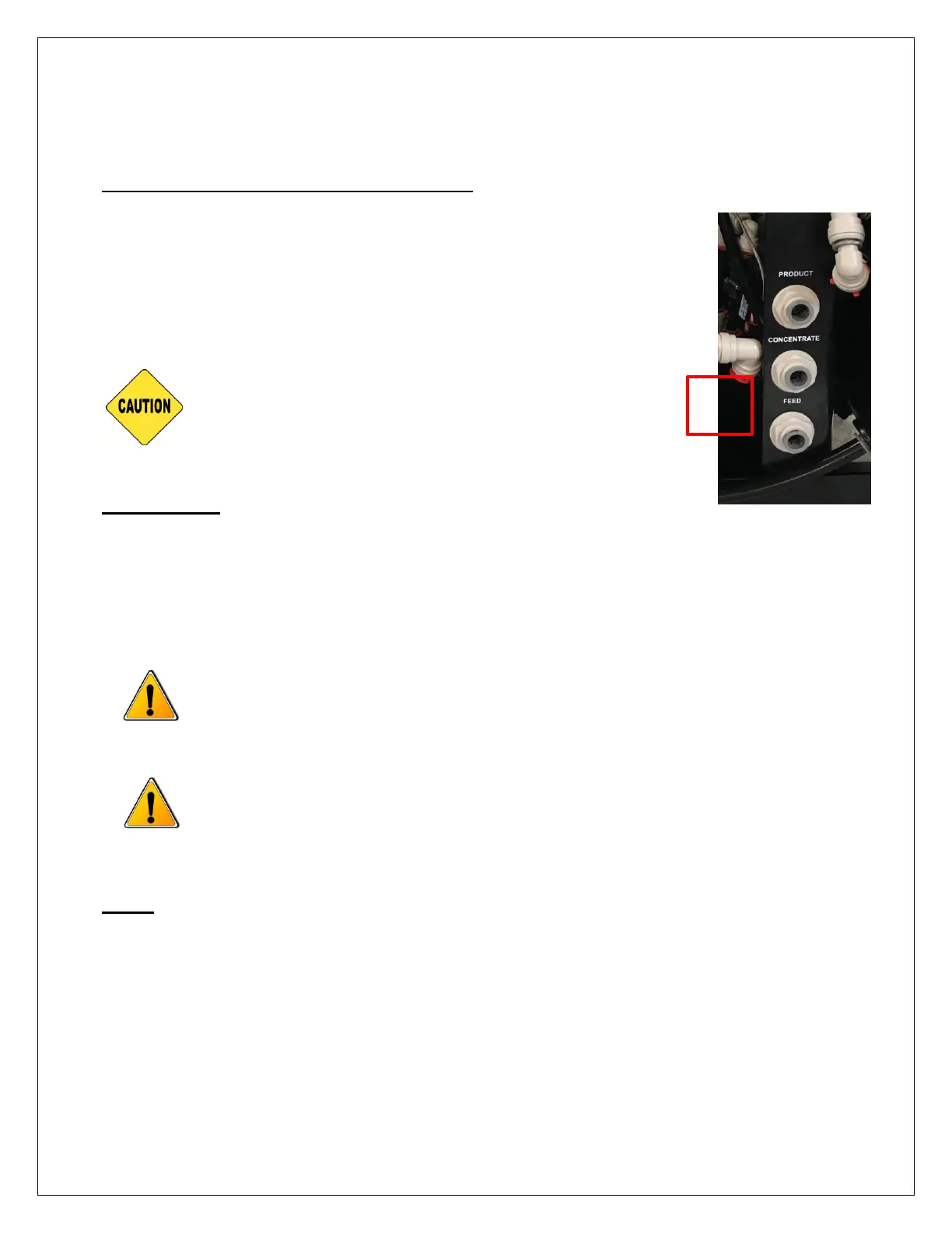
CONCENTRATE 1/2" QC FITTING (DRAIN)
Locate the 1/2” port on the right side of the system labeled
“CONCENTRATE”. Run the concentrate line to an open drain in a free
and unrestricted manner (no back pressure).
ANY RESTRICTIONS OR BLOCKAGE IN THE DRAIN LINE
CAN CAUSE BACK PRESSURE, WHICH WILL INCREASE
THE SYSTEM’S OPERATING PRESSURE. THIS CAN
RESULT IN DAMAGE TO THE SYSTEM’S
MEMBRANES AND COMPONENTS.
ELECTRICAL
The Hydroid system is 110V, 60 Hertz Single Phase, 10.6 amps, and is equipped with an eight–
foot electrical cord.
Ensure that the electrical circuit supplying the system is compatible with the requirements of
the Hydroid.
TO REDUCE THE RISK OF ELECTRICAL SHOCK, THE INCOMING POWER
SUPPLY MUST BE A GFI OUTLET.
IT’S RECOMMENDED THAT THE SYSTEM HAVE A DEDICATED POWER
SOURCE.
TANK
Hydroid systems may be connected to a bladder tank or a storage tank with a float valve. The
float valve shuts off the system when the tank is full and opens when the water level in the tank
drops. Bladder tanks and storage tanks with float valves can be obtained by your local dealer
or distributor. If a storage tank with float valve is to be used, install it at this time.