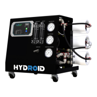
Hydroid – Series User Manual
15 04/19
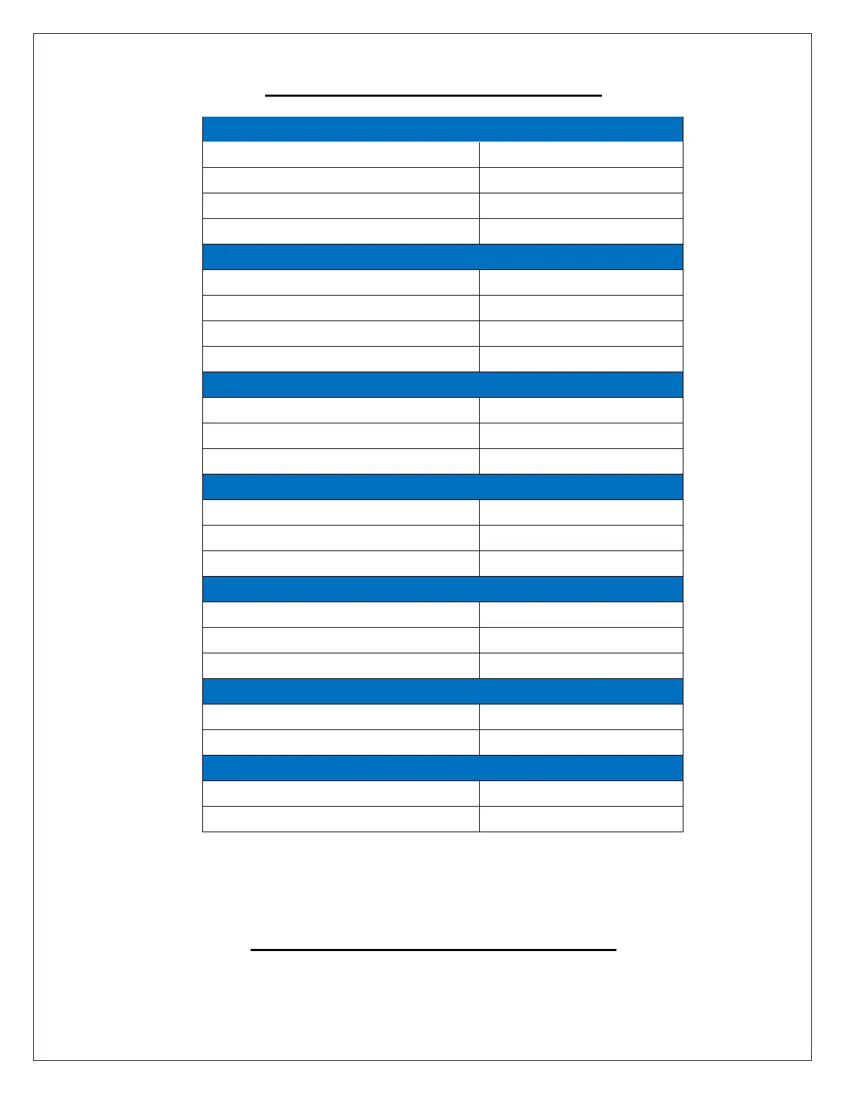
DESIGN BASIS AND DESIGN NOTES
System Recovery with Recycle
Rejection and Flow Rates
†††
PRODUCT Flow Rate (purified water)
CONCENTRATE Flow Rate (drain)
CONCENTRATE Recycle Flow Rate (drain)
PRODUCT Fitting (purified water)
CONCENTRATE Fitting (drain)
High Voltage Service + Amp Draw
Approximate Dimensions
††
(L x W X H)
Approximate Weight (Wet System)
††
Does not include operating space requirements.
†††
System Pressure is variable due to water conditions. PRODUCT (purified water) flow will increase
at a higher temperature and decrease at a lower temperature (see TCF Table on pg. 23).
††††
PRODUCT (purified water) flow and maximum recovery rates are based on feedwater conditions
as stated above.
SYSTEM PURGING / INITIAL START–UP
LEAVE THE SYSTEM UNPLUGGED FROM POWER UNTIL STEP 6