Page 12 of 36 Pages
Bleeding the System at Senders
After bleeding system at each slave bleeder valve, each
sender must now be bled. A small amount of air will be
trapped at the high point in each sender head.
1. Refill reservoir if required (fill tank at this time to between
1/2 and 2/3 full), and leave about 100 psi on the pressure
gauge.
NOTE
Place a rag over the bleeder hole on the
sender, to prevent fluid from spilling on the
console.
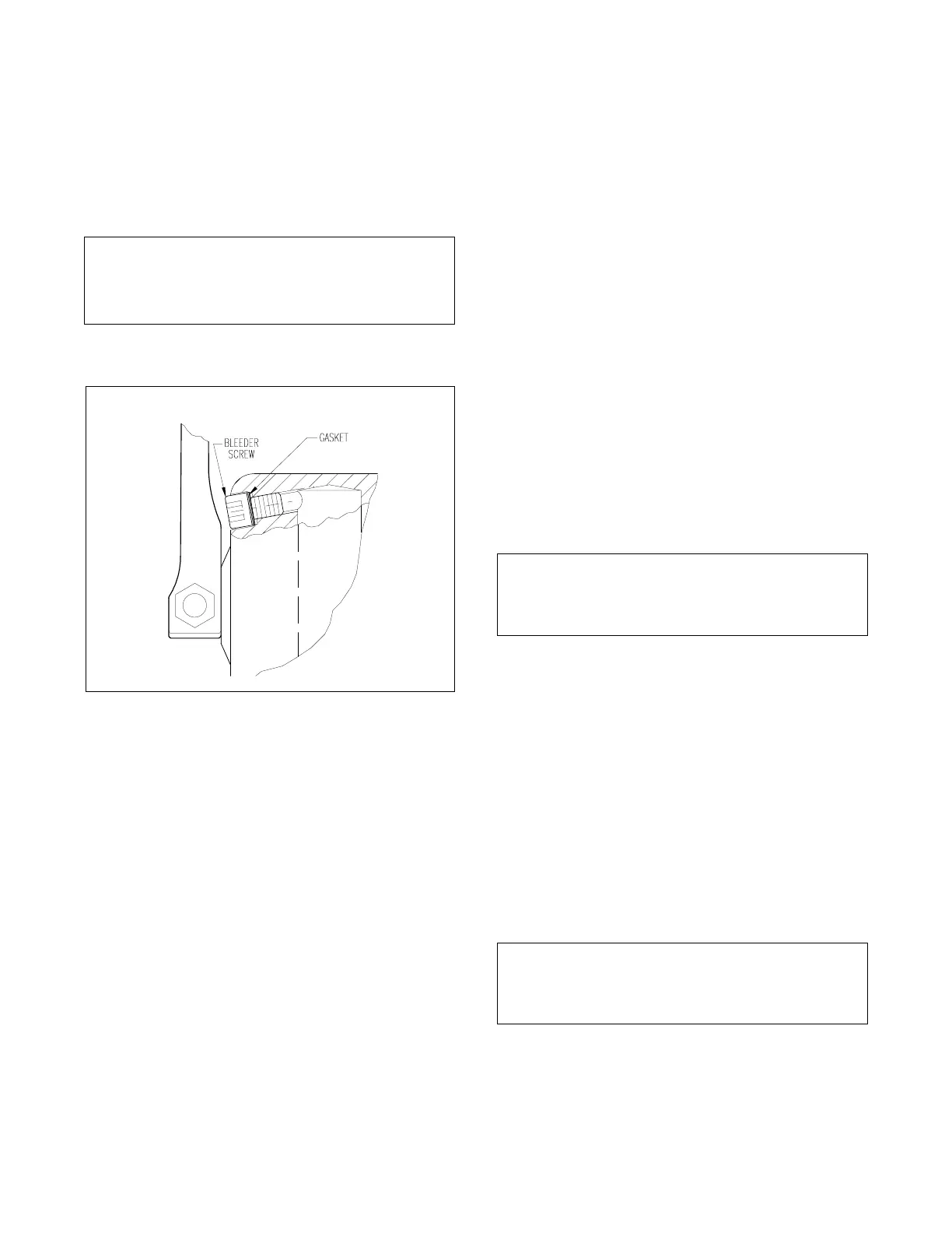
2. Very slowly open the bleeder plug using a 3/16" allen
wrench. See Figure 10 for location of bleeder screw.
3. Allow the fluid to bleed out until the fluid is clear without air
bubbles.
4. Tighten the bleeder screw after bleeding.
5. Repeat Steps 1 to 4 above, for each sender.
6. The reservoir level should be between 1/2 and 2/3 full. If
the level is below this, the reservoir should be filled to this
level. Verify that pressurize in the reservoir is between
80 and 85 psi.
System Fluid
The fluid recommended for use in the system is a 50/50
mixture by volume of distilled water and ethylene glycol. The
type of ethylene glycol used is very important for proper
operation of your system and especially the synchronization
(charging) valve. Some additives, especially silicone addi-
tives, are very thick in consistency and will clog the elements
in the synchronization valve. If this occurs your system will
be unable to maintain synchronization between sender and
slave.
The ethylene glycol chosen for use should be as pure (no
additives) as possible, proportionately mixed with distilled
water then filtered to assure its purity. NEVER USE STOP-
LEAK TYPE ANTI-FREEZE.
Filtration is accomplished by passing the fluid through a 5
micron filter before using in the system.
Field service pre-filtering can be accomplished by using a
“Mr. Coffee”or equivalent paper filter placed in a funnel and
then pouring the ethylene glycol solution through it.
One paper filter will filter approximately 1/2 gallon ` of
ethylene glycol solution.
The MCO-03 fluid provided by Morse is proportionately
mixed and filtered to assure its purity and is ready for use.
Making the System Operational
Synchronizing the Controls
The system is now operational except for synchronizing the
controls.
1. Go to one control station and move each sender’s arm
from stop to stop, 3 to 5 complete cycles. Each sender should
be synchronized at this time.
NOTE
This synchronization can be performed at any
of the control stations.
2. If the position of the sender’s handle requires an awkward
motion by the user, adjust the handle by loosening the set
screw (using a 1/4" allen wrench) and rotating the handle so
that the user has more of a direct push-pull motion. Do not
position handle so that it binds against the sender body at
either end of its stroke.
3. Should one of the controls not come into synchronization,
go to that station which is out of synchronization and perform
Step 1.
Connecting Engine Controls
1. Connect throttle linkages to the throttle slave. Repeat for
both engines.
2. Connect clutch linkages to the clutch slave. Repeat for
both engines.
NOTE
For any operational problems at this point,
consult the trouble shooting section.
Operation
Throttle Senders
Forward Motion — Increases Throttle.
Aft Motion — Decreases Throttle.
Figure 14. Bleeder Screw

 Loading...