Page 10 of 36 Pages
Rules for Routing Tubing
NOTE
The instructions and illustrations in this section
apply to nylon tubing ONLY. Information on
use of Copper Tubing may be found on page 12.
1. Keep tubing free of dirt and foreign matter.
2. Keep tubing away from batteries, since battery acid is
corrosive to the tubing.
3. Tie the tubing down at regular intervals using non-metallic
ties and clamps.
4. Do not allow tubing to become kinked. If it does, replace
that particular run of tubing.
5. String tubing so that it will not interfere with hatchways or
machinery removal.
6. Use only nylon tubing supplied with system from Morse.
Assemble tubing connectors on every tube end as described
and illustrated in Figure 13.
NOTE
The roll of tubing should be laid in a horizontal po-
sition and moved as little as possible to avoid
kinking and tangling.
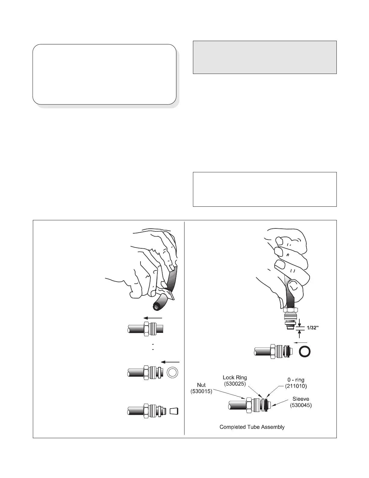
4. Insert the sleeve (530045)
in the tube until it just makes
contact all around.
3. Push the lock ring
(530025) over the end of the
tubing and move it back at
least one sleeve length from
the end. The lock ring may
slide on freely or require
slight pressure and "screw-
on" action. (The lock ring
has a left hand thread.)
6. Install the 0-ring (211010)
over the end of the tubing
and against the lock ring
(530025).
CAUTION
Dirt and foreign matter in the hydraulic
system cause damage and malfunction. It
is extremely important to keep tubing and
fittings clean when installing and connect-
ing components. Cut tube cleanly and
tape the open end while running tubing.
Four tubing installation plans are provided in the Tubing
Diagrams Section later in this manual:
1. Twin Engine, One Station, (Plan I)
2. Twin Engine, Two Station, (Plan II)
3. Twin Engine, Three Station, (Plan III)
4. Twin Engine, Four Station, (Plan IV)
Before beginning to run the tubing, it is recommended that
each tube be assigned a number which is marked on both
ends, and correspondingly, marked at the origin and desti-
nation of that tube. These designations should also be
recorded on the chosen plan diagram for future reference.
Figure 13. Assembling Tubing Connectors
1. Cut the tubing with a ra-
zor or very sharp knife, leav-
ing the cutoff end as square
as possible.
2. Slip the nut (530015) over
the tubing end. The nut
should slide freely.
5. Force the sleeve (530045)
into the end of the tubing by
pushing it against a clean,
flat surface. Thread the lock
ring (530025) toward the end
of the tube as far as pos-
sible by hand. Leave suffi-
cient room between the lock
ring and the end of the
tube to install theO-ring
(211010).
Tubing Installation and Connection
 Loading...