Page 4 of 36 Pages
with a pilot check valve which locks the throttle slave in the
position it has taken in response to the sender. The throttle
slave can be driven only by the sender, it cannot drive the
sender.
Extra hydraulic fluid and a pressure head for the system is
maintained by the system’s reservoir. The reservoir is charged
with 80 psi of air over the hydraulic fluid within it. This keeps
the entire system under pressure at all times and prevents a
vacuum from existing on the back side of any piston when the
system is operated.
Fluid-flow to and from the reservoir is regulated by a charging
valve located on the bottom of the reservoir. This valve is
necessary to keep the system under pressure, and to pre-
vent excessive pressures caused by the expansion of fluid
when the fluid becomes warm.
Nylon tubing is used to pipe the system for two reasons: (1)
ease of installation, (2) nylon tubing expands and contracts
in very much the same manner as the hydraulic fluid (a most
important factor). The expansion and contraction of the
tubing reduces drift of the controls as temperature changes,
thereby helping to keep all the components of the system
synchronized. The tubing is virgin nylon, which has been
heat and light stabilized and contains no plasticizers. The
burst pressure of the tubing is in excess of 1200 psi.
Teleflex Morse Engine Control System—
Why it Works
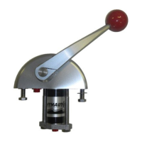
The movement of a sender’s control arm transmits mechani-
cal energy to an internal piston which in turn pushes hydrau-
lic fluid through the other corresponding control senders and
single control slave. This movement of hydraulic fluid drives
a piston in each of the senders and slave. The movement of
the individual pistons causes shaft rotation in each unit.
The piston in each of the individual control senders and
slaves has two small valves which are opened when the
piston reaches the end of its stroke, allowing additional fluid
to pass through the system. By allowing this flow of hydraulic
fluid, the controls may be synchronized with each other by
moving the control arm at one control station from stop to
stop.
The control slave is very similar to the control sender, except
the body is a rectangular block. An over-travel bungee is
used in the linkage between the slave arm and engine control
arm to assure that the slave can reach the end of its stroke
in each direction. The slave for the transmission has a built-
in detent mechanism to indicate neutral position.
On most engines the throttle exerts considerable force to
return to the idle position. Each throttle slave is equipped
Preparation for Installation
Before installation is started, the parts list should be checked
to verify that a complete system has been received. Parts
lists are located on pages 14 and 15.
It is advised that all system components be installed, (send-
ers, shift, throttle slaves, and reservoir) prior to running the
system tubing. This allows the tubing to be run between two
definite points with less chance of an error.
Should it become necessary for the tubing to be strung first,
a system of marking the different tubing runs should be used.
Use Loctite ® hydraulic sealant on all NPT fittings prior to
installation. DO NOT use teflon tape or pipe dope.
Sender Installation
1. Locate sender on panel so that the control arm’s arc will not
interfere with the ship’s wheel or panel. Be certain that
access is available to the small bleeder screw at the top of
each sender head.
The design of the new Engine Control "T" handle requires a
minimum distance between control heads to provide ad-
equate handle clearance when two sets of controls are
mounted side by side. See Figure 1.
NOTE: This minimum distance does not apply to installa-
tions using the optional "knob" style control handles.
2. Using the template provided in the appendix, mark and cut
a hole for the sender. Figure 29 is the proper template for the
single head and Figure 30 for the side by side sender
mounting. Refer to Figure 1 for minimum distance required
when mounting two sets of controls side by side.
3. Drill 7/16" holes in the panel for the mounting bolts.
4. Set sender in place and check to see if all mounting holes
match up.
5. The sender’s ports are tapped 1/4" NPTF. Suitable adapt-
ers must be installed to accept the tubing used. It is more
convenient to install these adapters prior to mounting the
senders. (Instructions for copper tubing installations are on
page 12.)
CAUTION
Dirt and foreign matter in the hydraulic system
cause damage and malfunction. It is extremely
important to keep tubing and fittings clean
when installing and connecting components.
Cut tube cleanly and tape the open end while
running tubing.
Component Installation
Components have red plastic plugs installed in their ports to
keep out foreign matter. As you remove these red plastic
plugs, replace them immediately with the proper adapter;
then install the red plugs into the adapters until you are ready
to connect tubing.

 Loading...