Page 5 of 36 Pages
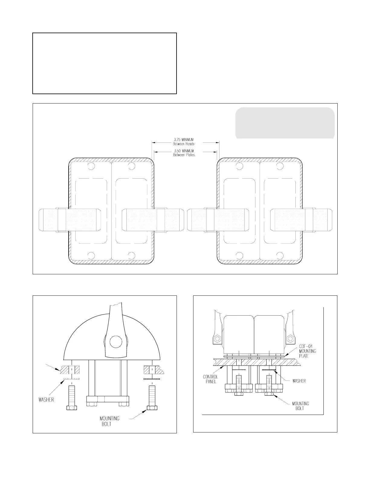
Figure 1. Mounting "T" Handle Controls Side by Side
NOTE
The minimum distance does not ap-
ply to installations using the "knob
style" control handles.
8. Secure the remaining senders per Steps 1 thru 7.
Figure 2. Single Head Sender Figure 3. Side-By-Side Senders
NOTE
If the area under the control panel is too confined to
allow the tubing to be connected with moderate
ease, do not secure the sender at this time. Proceed
with the installation of the remaining senders per
Steps 1 thru 5 above. The sender may be secured
after the tubing has been connected to it.
6. Secure senders per Figure 2 for single head, or Figure 3
for side by side mounting.
7. The sender’s handle position may be set within limits by
loosening the tightening screw (using a 1/4" allen wrench) in
the lower end of the arm and then rotating the arm as desired
and resetting the screw. After the arm is set, it will have a 115°
maximum arc.
 Loading...