EasyManua.ls Logo

Hynautic 04 Series - User Manual

Hynautic 04 Series
36 pages
Print Icon
To Next Page IconTo Next Page
Loading...
Page 1 of 36 Pages
Hydraulic
Engine Controls
Installation and Service
-04 SERIES
CAUTION!
THIS SYSTEM DOES NOT USE OIL.
Use 50/50 (by volume) ethylene-glycol/distilled water
DO NOT USE STOP-LEAK TYPE ANTI-FREEZE
THIS MANUAL SHOULD BE KEPT ON BOARD YOUR VESSEL
182042 Rev.4
8/02
Question and Answer IconNeed help?

Do you have a question about the Hynautic 04 Series and is the answer not in the manual?

Hynautic 04 Series Specifications

General IconGeneral
BrandHynautic
Model04 Series
CategoryControl Unit
LanguageEnglish

Summary

Hydraulic Engine Control System Overview

System Functionality Explained

Explains how the Teleflex Morse hydraulic engine control system operates and its core principles.

Installation Preparation Steps

Details the essential preliminary steps before installing the hydraulic engine control system.

Component Installation Guidance

Provides instructions on how to properly install the various components of the system.

Throttle Slave Installation Procedures

ST-06 Model Installation

Specific installation instructions for the Teleflex Morse ST-06 throttle slave.

ST-04 Model Installation

Specific installation instructions for the Teleflex Morse ST-04 throttle slave.

Clutch Slave Installation

Reservoir and Charging Valve Installation

R-13 Reservoir Setup

Instructions for installing the R-13 reservoir and its associated components.

R-04 Reservoir Setup

Instructions for installing the R-04 reservoir and its associated components.

MCV-04 Charging Valve Setup

Instructions for installing the MCV-04 charging valve.

Tubing Installation and Connection

Guidelines for Routing Tubing

Provides recommendations and rules for properly routing hydraulic tubing.

System Filling and Bleeding

Install Tubing Between Senders and Slaves

Detailed steps for running and connecting tubing between control components.

Filling the System

Procedure for filling the hydraulic system with the correct fluid.

Bleeding the System at Slave

Instructions for bleeding air from the system at the slave components.

System Fluid and Operation

Bleeding the System at Senders

Procedure for bleeding any remaining air from the system at the sender units.

System Fluid Specifications

Details the recommended hydraulic fluid mixture and type for system operation.

Making the System Operational

Steps to make the installed hydraulic system ready for use.

Control Operation Details

Covers synchronizing controls, connecting linkages, and sender operation.

Maintenance Schedule

Copper Tubing Installation

System Parts List - Nylon Tubing

System Parts List - Copper Tubing

Sender Assembly Components

Handle Installation

Ball and Tee Handle Installation

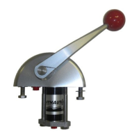
Specific instructions and torque values for installing ball and tee style handles.

ST-06 Throttle Slave Parts Breakdown

Transmission Slave Assembly Parts Breakdown

Neutral Safety Switch Kit Installation

Mounting Templates and Plates

Single Head Mounting Template

Template for drilling holes for single sender head mounting.

Side-by-Side Mounting Template

Template for drilling holes for side-by-side sender head mounting.

CDF-04 Mounting Plate Installation

Tubing Circuits: Plan I

Twin Engine, One Station Configuration

Diagram and description for a twin engine, one station hydraulic tubing circuit.

Tubing Circuits: Plan II

Twin Engine, Two Station Configuration

Diagram and description for a twin engine, two station hydraulic tubing circuit.

Tubing Circuits: Plan III

Twin Engine, Three Station Configuration

Diagram and description for a twin engine, three station hydraulic tubing circuit.

Tubing Circuits: Plan IV

Twin Engine, Four Station Configuration

Diagram and description for a twin engine, four station hydraulic tubing circuit.

Supplemental Throttle Control Circuits

Plan I-S: Single Station Counterclockwise

Diagram for single station throttle control with counterclockwise advance.

Plan II-S: Two Station Counterclockwise

Diagram for two station throttle control with counterclockwise advance.

Supplemental Throttle Control Circuits (Continued)

Plan III-S: Three Station Counterclockwise

Diagram for three station throttle control with counterclockwise advance.

Plan IV-S: Four Station Counterclockwise

Diagram for four station throttle control with counterclockwise advance.

Troubleshooting Common Issues

Troubleshooting Common Issues (Continued)