Page 9 of 36 Pages
Figure 10. Charging Valve on R-13 Reservoir
The reservoir should be located in the ship’s engine room in
an accessible location. In locating the reservoir the following
conditions should be met:
1. Reservoir must be in a vertical position with pressure
gauge on top.
2. Sight glass must be visible and easy to read.
3. Pressure gauge be visible and easily read.
4. The operator must have easy access to the air filler valve
on the top of the tank.
5. The operator must have easy access to the fill port on top
of the tank.
6. Reservoir must be mounted to the bulkhead, wall or post
using either bolts or screws.
R-04 Reservoir Installation
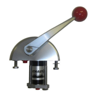
Figure 12. MCV-04 Charging Valve
Reservoir Installation
NOTE
The standard Morse System, MC-04, uses
the R-13 Integrated Reservoir. You may
have a different system which includes the
R-04 Reservoir and an MCV-04 Charging
Valve. Depending on which system you
have, follow the corresponding installa-
tion instructions in this section.
NOTE
There are two ports located on the bottom of the
reservoir. One is plugged and can be used as a
drain port. The other has a filter assembly and is
used for connecting to the system. See Figure 11.
Figure 11. Ports on Bottom of R-04 Reservoir
MCV-04 Charging Valve Installation
The charging valve should be located in the general vicinity
of the reservoir.
1. Install appropriate adapters for the tubing used. For port
locations see Figure 12.
2. Mount the charging valve using two screws or bolts.
The reservoir should be located in the ship’s engine room in
an accessible location. In locating the reservoir the following
conditions should be met:
1. Reservoir must be in a vertical position with pressure
gauge on top.
2. Sight glass must be visible and easy to read.
3. Pressure gauge must be visible and easily read.
4. The operator must have easy access to the air filler valve
on the top of the tank.
5. The operator must have easy access to the fill port on top
of the tank.
6. The operator must have easy access to charging valve on
bottom of reservoir.
7. Reservoir must be mounted to the bulkhead, wall, or post,
using either bolts or screws.
NOTE
The charging valve is located on the bottom of
the reservoir. The plug located on the charg-
ing valve holds the fluid filter in place. This
plug and filter can be removed to drain the
reservoir’s fluid. See Figure 10.
R-13 Reservoir Installation
NOTE
If your installation includes two reservoirs
(one for each engine), or is a single-engine
installation, special plumbing will required
which is not covered in this manual. Con-
tact Teleflex Morse for this information.
 Loading...