Page 8 of 36 Pages
Figure 9. SS-04 Shifter Slave - Bleeder Valve and Tubing Adapters Installation
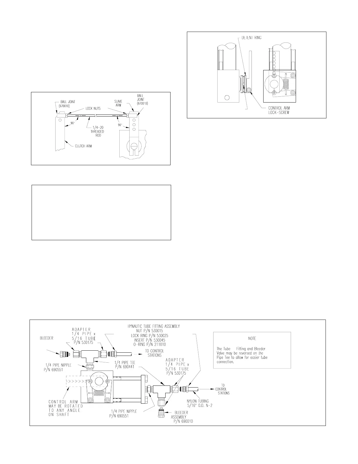
5. Secure detent ring in this position by tightening the set
screw.
6. Install a lock nut and ball joint on the end of the 1/4-20
stainless steel or brass threaded rod.
7. Position the clutch slave to its mid-stroke and connect the
ball joint end of the 1/4-20 threaded rod to it.
8. Position the engine’s clutch arm to neutral, determine the
proper length of the threaded rod required and cut off the
excess.
9. Install a lock nut and ball joint on the other end of the
threaded rod.
10. By locating the slave arm ball-joint in its proper hole and
adjusting both ball joint on the threaded rod, find the correct
length of linkage that will allow both "full- forward" and "full-
reverse" on the transmission for full throw on the clutch slave
arm.
11. After determining the correct linkage length, securely
lock the ball-joints to the threaded rod with lock-nuts pro-
vided. Disconnect the linkage from the clutch slave’s arm.
12. Locate and secure in place two tees, two bleeder valves,
and two tubing adapters, per Figure 9.
13. Repeat this clutch slave installation procedure for the
second engine.
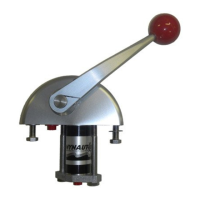
Figure 7. Proper Clutch Slave to Throttle Arm
Installation
Clutch Slave Installation
The Morse clutch slave must be mounted so that when the
engine’s transmission is in neutral and the Morse clutch
slave’s arm is at its mid-stroke, both arms will be: 1) in the
same plane; 2) parallel to each other; and 3) right angles will
be formed between connecting linkage and each arm, see
Figure 7.
NOTE
The clutch slave’s arm may be set to any
desired position by loosening the tightening
screw (using a 3/16" allen wrench) in the lower
end of the arm. Rotate arm as desired and
reset the screw. After the arm is set it will have
a 78° maximum arc.
1. Secure mounting bracket to the engine. A suitable bracket
must be fabricated.
2. Secure the transmission slave to the mounting bracket
using the 3/8-16 mounting bolts.
3. Set the transmission in the neutral position, and the clutch
slave’s arm at its mid-stroke.
4. Loosen the set screw in the detent ring on the clutch slave
and rotate the detent ring to the full detent position. To locate
the detent ring, see Figure 8.
Figure 8. Detent Ring Location
▲
▲
 Loading...