Page 7 of 36 Pages
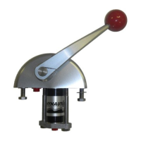
Figure 6. ST-04 Throttle Slave with STV-10 Lock-Out Valve
NOTE
If the throttle slave is in a limited space, it may
be removed from the bracket during the lock-
out valve installation. The STV-10 lock Out
Valve must be plumbed as shown in Figure 6.
The lock-out valve will lock the slaves arm
and allow it to be moved by only the sender.
The check valve and slave must be mounted in
close proximity to one another. If they're not,
abnormal locking action and poor performance
will result.
10. Install the lock-out valve on the throttle slave and
secure it using clean lubricant or Loctite hydraulic sealant on
the threads. Install appropriate adapters to accept tubing.
Refer to Figure 6.
Figure 5. ST-06 Integrated Throttle Slave with Tee and Bleeder Valve Installation
NOTE
Tube connectors are installed on the tubing
per instructions under “Tubing Installation”
and “Connection.”
11. Using a short piece of tubing provided, connect the open
port on the tee to the S2 port on the lock-out valve. See
Figure 6. (See Figure 16 for Copper Tubing connection.)
Plug open fittings at the V1 and V2 ports.
12. Verify all fittings installed have been tightened. Repeat
these throttle slave installation procedures for the second
engine.
CONTROL ARM MAY BE ROTATED
TO ANY POSITION ON SHAFT
CONTROL ARM MAY BE ROTATED
TO ANY POSITION ON SHAFT
 Loading...