Page 6 of 36 Pages
Steps 1 thru 8 apply to both ST-04 and ST-06 Systems
1. Secure the mounting bracket to the engine. A suitable
bracket must be fabricated.
2. Secure the throttle slave to the mounting bracket using
3/8-16 mounting bolts.
3. Install a lock nut and bungee-ball joint on the end of a
1/4-20 stainless or brass threaded rod.
4. Position the throttle slave to its mid-stroke and connect the
bungee end of the 1/4-20 threaded rod to it.
5. Position the engine’s throttle arm to its mid-stroke. Deter-
mine the length of threaded rod required and cut off the
excess.
6. Connect a lock nut and a ball-joint to the engine’s throttle
arm and the free end of the threaded rod.
7. Find the proper hole in the slave arm to provide a linkage
length combination that will allow idle to full throttle on the
engine, using all but a few degrees of slave arm travel in each
direction. By adjusting the ball-joint and bungee, a fine
adjustment in both directions can be achieved. Be sure the
slave arm can over-travel through the bungee to the end of
its stroke in each direction.
8. After determining the correct rod length, securely lock the
ball-joint and bungee assembly to the threaded rod with lock
nuts provided. Disconnect the linkage from the throttle slave’s
arm.
ST-06 Installation Only
9. To prevent engine retard due to governor spring or
vibration, a pilot check valve is built into the ST-06 Throttle
Slave.
NOTE
This built-in valve will lock the slave arm in place
allowing it to be moved only by the sender
10. Locate a tee and bleeder valve on the throttle slave and
install suitable adapters to accept tubing, per Figure 5.
NOTE
Tube connectors are installed on the tubing
per instructions under “Tubing Installation”
and “Connection” on page 8.
11. Verify all fittings installed have been tightened. Repeat
these throttle slave installation procedures for the second
engine.
Throttle Slave Installation
NOTE
The standard Teleflex Morse System,
MC-04, uses the ST-06 Integrated Throttle
Slave. You may have chosen to order a
non-standard system which includes the
ST-04 Throttle Slave and STV-10 Lock-out
Valve. Depending on which system you
have, follow the corresponding installa-
tion instructions in this section.
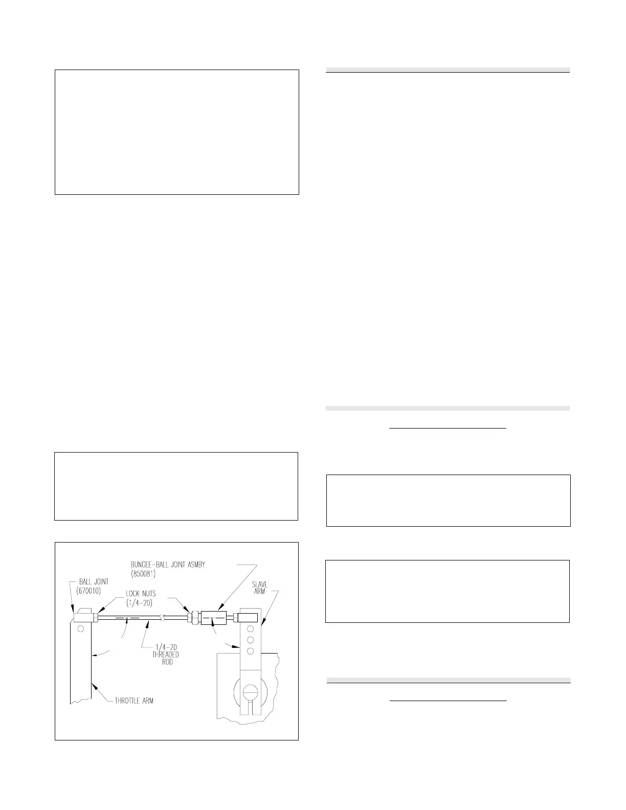
Figure 4. Throttle Slave to ThrottleArm Installation
ST-04 Installation Only
9. To prevent engine retard due to governor spring or
vibration, a separate STV-10 lock-out valve is used with the
ST-04 Throttle Slave.
Teleflex Morse throttle slaves must be mounted so that at the
mid-stroke of both the engine’s throttle arm and the slave’s
control arm, they are: 1) In the same plane; 2) parallel to each
other; and 3) right angles will be formed between the con-
necting linkage and each arm. See Figure 4.
If these criteria are met, an ideal installation will result.
A spring bungee-ball joint assembly is furnished with each
throttle slave. It is installed in the slave arm-to- throttle
linkage according to Figure 4. It allows up to 3/16" slave
arm over-travel in each direction. This over-travel lets the
slave cylinder travel its full stroke and still provide full travel
to the throttle arm. You must use almost all of the slave travel,
or about 75°, to operate the throttle. The slave must go full
stroke in each direction in order to synchronize the system.
The throttle slave’s arm may be set to any desired position by
loosening the tightening screw (using a 3/16" allen wrench)
in the lower end of the arm and then rotating the arm as
desired and resetting the screw. After the arm is set, it will
have a 78° maximum arc.
CAUTION
The Throttle Slave must not be mounted to
any surface exceeding 220° F (103° C). If
mounting in a "hot spot" is unavoidable, the
slave must be insulated from the heat.
 Loading...