Page 22 of 36 Pages
Optional Neutral Safety Switch Kit SSH-01
Installation Instructions
1. Before wiring the Switch, determine the best routing for the wires as they lead away from the switch.
2. Break out an appropriate knock-out in the Switch Cover and feed the wires through before placing cover on Switch. When
positioning the wiring be sure that it will not interfere with the mechanical function of the switch or slave.
2. Using the “common” and “normally closed” Switch Terminal Screws, wire the switch into the circuit between the Starter
Solenoid and the Starter Key Switch in accordance with the engine manufacturers recommendations.
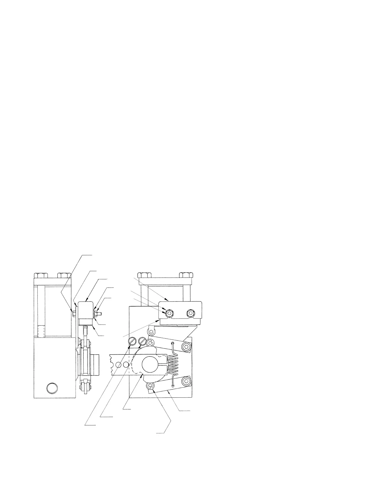
3. Using #6-32 screws (p/n 240857), #6 flatwashers (p/n 260147), #6 lock washers (p/n 260107), and #6-32 hex nuts (p/n
270177), mount Switch to Plate as shown in drawing. (Do not tighten screws at this time.)
4. Using #8-32 round head screws (p/n 240201) and #8 lock washers (p/n 260052), mount the Plate to the slave body as shown
in drawing. (Do not tighten screws at this time.)
5. Shift the transmission to “Forward” or “Reverse” so that the Cam Follower Wheels are out of the Detents and
the Arms are
in the “UP” position as shown in the drawing.
6. Make adjustments to the Switch and Plate so that the Switch makes contact when the slave arm is in the “UP” position.
7. After making necessary adjustments, tighten all four mounting screws. Be sure the slave arm does not cause too much
overtravel on the Switch causing possible damage to the switch arm.
1. Before wiring the Switch, determine the best routing for the wires as they lead away from the switch.
2. Break out an appropriate knock-out in the Switch Cover and feed the wires through before placing cover on Switch. When
positioning the wiring be sure that it will not interfere with the mechanical function of the switch or slave.
2. Using the “common” and “normally closed” Switch Terminal Screws, wire the switch into the circuit between the Starter
Solenoid and the Starter Key Switch in accordance with the engine manufacturers recommendations.
3.
Using #6-32 screws (p/n 240857), #6 flatwashers
(p/n 260147), #6 lock washers (p/n 260107), and #6-32 hex nuts (p/n
270177), mount Switch to Plate as shown in illustration. (Do not tighten screws at this time.)
4. Using #8-32 round head screws (p/n 240201)
and #8 lock washers (p/n 260052), mount the Plate
to the slave body as shown in drawing. (Do not
tighten screws at this time.)
5. Shift the transmission to “Forward” or “Reverse”
so that the Cam Follower Wheels are out of the
Detents and
the Arms are in the “UP” position
as shown in illustration.
6. Make adjustments to the Switch and Plate so
that the Switch makes contact when the slave arm
is in the “UP” position.
7. After making necessary adjustments, tighten all
four mounting screws. Be sure the slave arm does
not
cause too much
overtravel on the Switch
causing possible damage to the switch arm.
DETENT
240201 SCREW
260052 LOCKWASHER
CAM FOLLOWER WHEEL
ARM (shown in "up" position)
240857 SCREW
520524 SWITCH PLATE
870220 SWITCH
COVER
260147 FLAT
WASHER
270177 HEX
NUT
260107 LOCK
WASHER
870240 MICRO
SWITCH
 Loading...