© Copyright 2019 HYPERVSN. All rights reserved 13
Assembly procedure
Attention. Alternatively, the Device may be supplied pre-assembled. In this case, skip the steps of the Device
assembly procedure described in this section.
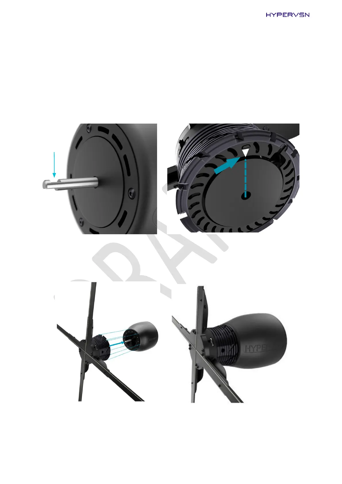
1. The indention in the shaft (marked with an arrow in the picture below on the left) needs to be
positioned against the white mark on the bottom of the rotor (marked with an arrow in the picture
below on the right).
Picture 8. Positioning the rotor (right) on the stator (left)
2. Carefully take the rotor (avoiding any damage to the rays) and gently place it straight onto the shaft as
shown below:
Picture 9. Fitting the rotor onto the shaft