www.hysecurity.com Congure the Operator D0559 Rev. A 25
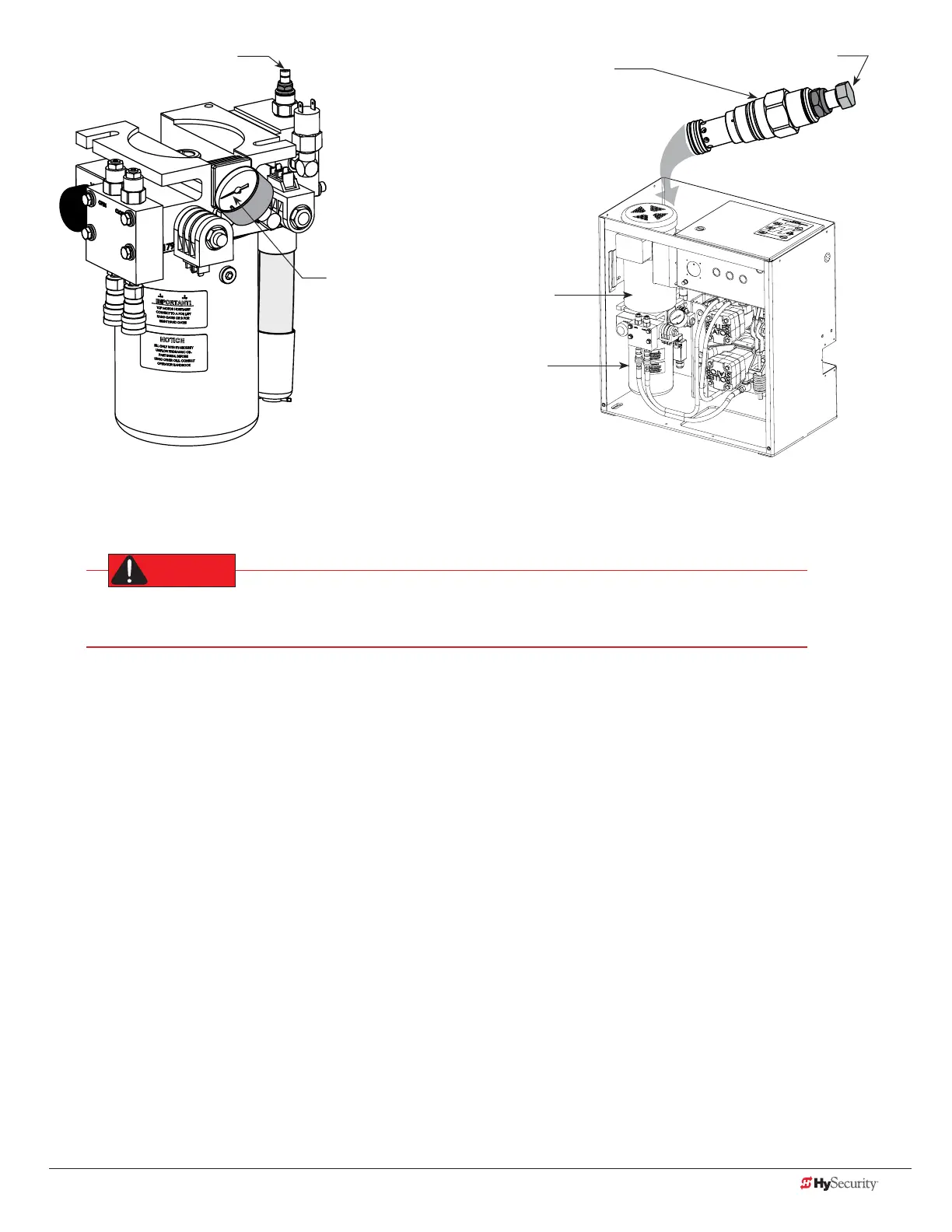
Adjustment Screw
SlideDriver 30F, 80, 200
Pressure
Gauge
Motor
Pump
pack
Adjustment Screw
SlideDriver 15, 40, 50VF
The Pressure Relief
Valve is located
behind the motor
on the pump rack or
soft start manifold.
Make sure the gate is properly installed and aligned before performing the following steps. Take precautionary
measures to keep the gate’s travel path clear. The gate will be moving while you adjust the pressure relief valve.
DO NOT attempt to adjust the pressure relief valve unless you are an experienced hydraulic gate
operator installer. Incorrect pressure settings can cause injury and even death!
1. Expose several threads on the Pressure Relief Valve by loosening the locknut with a 9/1 6 " box end wrench.
2. Depending on the model, insert a 5/3 2 " hex key or use a ½" box end wrench to turn the Adjustment Screw.
3. Use the keypad to cycle the gate open or close and, while the motor is running, turn the Adjustment
Screw clockwise (CW) to raise the pressure. The motor runs for a few seconds, stops, and then enters safe
mode. SAFE appears on the display.
4. Press RESET and repeat step 3 until gate travel is reliably consistent without entering SAFE mode.
5. To lock in the pressure setting, hold the Adjustment Screw with a hex key or wrench and tighten the
locknut.
 Loading...


