www.hysecurity.com General Maintenance D0559 Rev. A 91
Brake Valve Adjustments
Proper adjustment of the brake valves is important for smooth operation
of the gate. The position and placement of the limit ramps on the drive rail
plays an important part on how the brake valves work.
In order for the brake valves to have time to function, the limit ramp must
trigger the limit switch at least two inches before the point at when you
want the gate to stop.
Adjustment of the brake valves, one for each direction of travel, will
determine how quickly the gate actually stops. If adjustment is needed,
loosen the 9/16-inch lock nut on the top of the brake valve and make
¼-inch incremental turns on the adjustment stem with a hex key.
Note that the adjustment screw varies depending on model type.
The adjustment is counter-intuitive.
A counter-clockwise adjustment stops the gate more rapidly. If the
adjustment is set too loose, the limit ramps will bang into the drive wheels.
If the adjustment is set too tight, the system pressure will increase, the
gate speed may decrease and the gate will jerk to a stop.
Brake valves are factory-set to midpoint, two turns. This should be sufcient for most applications. If the limit
switch triggers and the drive rail stops more than two inches into the limit ramp, increase braking. When the
adjustment is complete, retighten the locking nut to hold the setting.
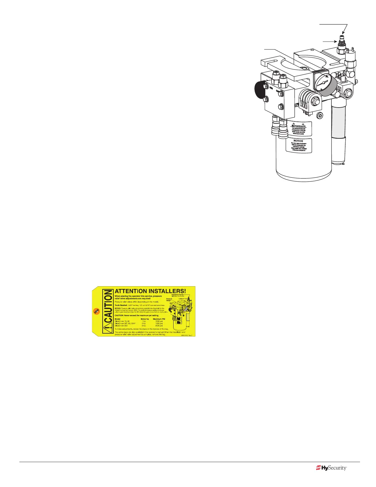
Pressure Relief Valve Adjustments
The Pressure Relief Valve governs the maximum system hydraulic pressure. It is located on the backside of the
pump. The pressure relief valve is factory set and may need to be adjusted depending on the gate weight. See
“Adjusting the Pressure Relief Valve” on page 24 or refer to the yellow tag wire tied to the unit and follow the
instructions.
Open Valve
The open valve is solenoid operated and, when energized, directs the hydraulic ow to open the gate. No
adjustment of this valve is possible or necessary. The black solenoid coil mounts on its valve stem.
Adjustment Screw
SlideDriver 30F, 80, 200
Locknut
Pressure
Gauge