46 D0559 Rev. A SlideDriver/SlideDriver 50VF Series www.hysecurity.com
settIng tHe Close tImer
As an added security measure, set the Close Timer. This ensures that the Security gate closes automatically within
a reasonable time frame, after all loops are cleared.
The Close Timer assigns how many seconds will pass before the gate operator initiates closure of a fully opened
gate after all open commands and reversing sensor inputs have ceased and loops cleared. Every gate operator
needs to have the close timer set to a specic number of seconds (for example, 5 seconds) unless a hard-wired
closing device is connected to the unit, such as a “hold to close” push button station.
To adjust the time (1 to 99 seconds) it takes before the operator initiates gate closure, take the following steps:
1. At a gate status display, press the Menu button twice. This accesses the User Menu and the Close Timer
display appears.
NOTE: If you want gate personnel to operate the gate with the Hold to Close feature found in some push
button stations, then set the Hold to Close menu item to 1. When the Hold to Close menu item is active
(set to 1), the Close Timer menu item is unavailable.
2. Use the Select, and then Next or Previous buttons to navigate and change the number of seconds
appearing on the display. Refer to Menu Mode Navigation on page 36.
3. To exit the User Menu, press the Menu button. The gate status appears in the display indicating you have
returned to Run Mode.
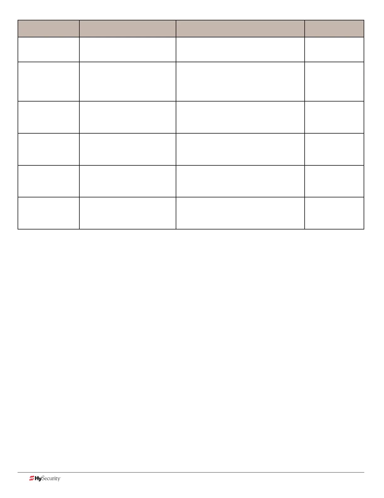
Installer Menu Setting Options Menu Tasks & Explanations STC Wire
Connections
SA 0 (OFF)
STC ADDRESS
0 = No network
1 to 99 = Network “drop” address
Sets the system address for network
communication: 0 = no network communication
1-99 sets individual poling addresses.
RS-485. Involves
additional hardware
& software.
NE 0 (OFF)
NETWORK SETUP
0 = No network (off)
1 = Network address (on)
Menu item appears when SA is not set to zero (0).
If a system address exists a setting of 1 opens the
network conguration menu.
0 = no network communication
1 = allows conguration of network addresses.
RS-485. Involves
HyNet™ & software.
ELD0 RUN MODE
EXIT LOOP SET
0 = Run mode
1 = Show frequency
2 = Show call level 0-7
3 = Set Frequency
Controls the HY-5A Free Exit loop detector. HY-5A
ILD0 RUN MODE
IND OBS LOOP SET
0 = Run mode
1 = Show frequency
2 = Show call level 0-7
3 = Set Frequency
Controls the HY-5A Inside Obstruction Loop
detector.
HY-5A
OLD0 RUN MODE
OUT OBS LOOP SET
0 = Run mode
1 = Show frequency
2 = Show call level 0-7
3 = Set Frequency
Controls the HY-5A Outside Obstruction Loop
detector.
HY-5A
SLD0 RUN MODE
SHADOW LOOP SET
(Reset Loop Set)
0 = Run mode
1 = Show frequency
2 = Show call level 0-7
3 = Set Frequency
Controls the HY-5A Shadow Loop detector. HY-5A
 Loading...


