8
5.0 Installation
Important! A licensed electrician is required to install the Apollo 5K in any
hardwired fashion. An Apollo 5K Wiring Box (Optional Purchase) may be used in
the installation. For all configurations, please consider the rated amperages of
power sources, total loads, wires, and the Apollo 5K. Do not exceed limits.
The Apollo 5K factory default setting is “floating neutral” (i.e. the neutral and
ground are unbonded.
The unit should be configured with floating neutral when connecting the load
side of the Apollo to a separate ground (e.g. directly supplying power to a home
breaker panel).
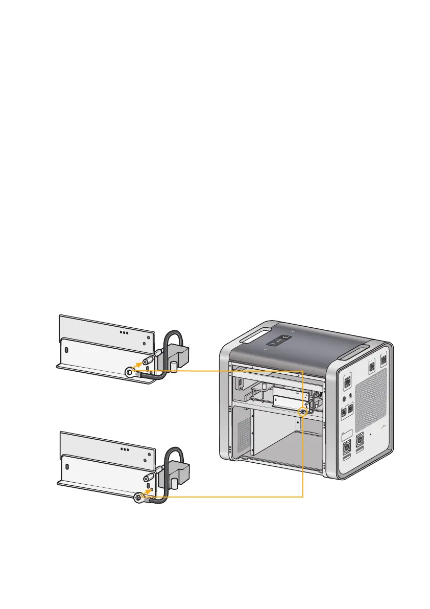
The unit may be configured with a neutral-ground bond, a.k.a. “bonded
neutral”, which may be preferred for some o-grid applications. To bond the
neutral to the ground, please follow instructions according to the label on the
side panel of the Apollo as depicted in Fig. 5.1 and Fig. 5.2 below.
The Apollo ground port may be connected to a grounding rod, building rod, etc.
by a qualified electrician. Ensure the Apollo neutral-ground is appropriately
bonded or unbonded.
BATTERY 2
51.2VDC
BATTERY 2
51.2VDC
RESET RUN ALM C HARGE
AC OUTPUT COMM.P ORT
110V/120V
MAX 35A
AC INPUT
WARNING!
COM1 COM2
DO NOT CONNECT DIFFEREN T TYPE
OF BATTERY! WRONG BATTERY MAY
DAMAGE THE WHOLE UNIT. THE
EXPANSION BATTERY PACK MUST
BE SUPPLIED BY THE ORIGIN AL
MANUFACTURUR.
I
n
v
e
r
t
e
r
R
e
s
e
t
S
w
i
t
c
h
A
C
I
n
p
u
t
R
e
s
e
t
S
w
i
t
c
h
120V~450V DC
MAX 5000W
SOLAR INPUT
12V/24V
MAX 10A
DC INPUT
Fig. 5.1 Neutral-Ground Separated /
Floating Neutral (Factory Default): The
Neutral wires to the plastic pole
Fig. 5.2
Neutral-Ground Bonded: The Neutral
wires to the metal structure