TC-508 Service Manual
14
TX/RX
VCO
Q102
POWER
MATCH
ANT LPF
APC
U401
VT
LO
VT
POWER AMP
Q403
RD07
POWER AMP
Q402
RD01
POWER AMP
Q401
2SC4226
LOCAL OSCILLATOR AMP
Q104
2SC5108
SW
Q405
DTC114EE
T/R SW
Q103
D105
VR SW
D405
VT SW
D404
APC_SW
Q404
DTC114YE
APC
T/R
LOCAL OSCILLATOR AMP
Q406
2SC4226
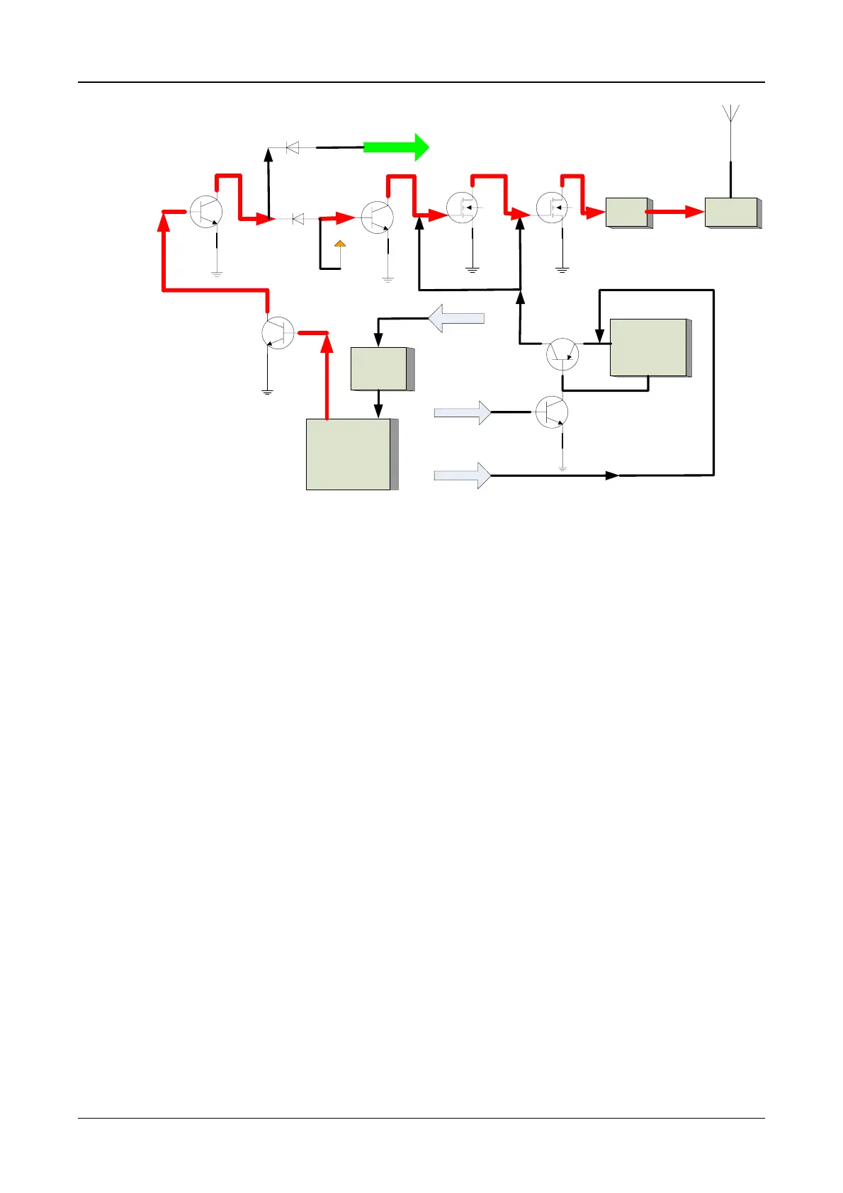
Figure 3
The modulated carrier signal from VCO is pre-amplified at Q104 and Q406, and controlled at D404
and D405. Then it is amplified by the front-stage amplifier Q401, the pre-driver Q402 and the final-stage
amplifier Q403 orderly. Finally it will be transmitted via antenna after ultra harmonics are removed by the
LC low-pass filter circuit.
APC circuit is composed of Q404, Q405 and U401. U401 controls the bias voltage at the gates of
Q402 and Q403, to control TX current and to further regulate power.
2.3 RX LNA and Mixer Circuit (RX Section)
The Block Diagram of RX Circuit is shown as below:

 Loading...