3-6
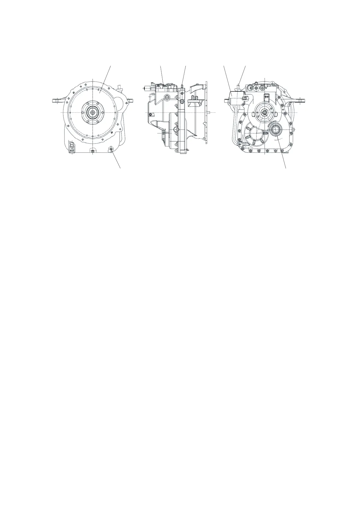
INSTALLATION VIEW
1 3 564
27
15L7APT05
2)
1 Torque converter
2 Temperature sensor
3 Control valve
4 Oil level pipe and dipstick
OPERATION
The torque converter is an automatic fluid drive.
It transmits engine torque by means of hydraulic force.
The torque converter leads and the power which is delivered rotated the charging pump.
Oil is drawn from the transmission reservoir by the charging pump.
The pump delivers its entire output to a full-flow oil filter for cleaning.
From the oil filter, the oil supply is sent to the control valve.
The main pressure regulator valve provides pressure for clutch pack, directs oil to the solenoid
valve.
Moving the solenoid valve allows oil to charge the selected (forward or reverse) clutch line and to
engage that clutch.
The remaining oil appropriating clutch pressure flows into the torque converter.
A converter pressure regulator valve in the converter-in line limits the oil pressure there.
The oil pressure input to the torque converter is adjusted 4~7
kgf/cm
2
(57~100
psi
).
The oil pressure output from the torque converter is adjusted below 2~4.5
kgf/cm
2
(28.4~64
psi
).
The torque converter is continuously filled with oil during operation.
Rotation of the converter impeller imparts energy to the oil which, in turn, drives the turbines.
The oil then flows between the stator vanes which redirect it to the impeller.
At this time, torque is increased.
The oil from the torque converter enters the cooler.
The cooler is a heat exchanger in which the oil flows through air cooled passages.
After refrigerated, it is in charge of clutch lubrication through the lubrication oil path of the clutch
shaft. A lubrication valve between the cooler and lubrication system returns all excess oil to the
transmission reservoir.
3)
5 Air breather
6 Transmission oil filter
7 Transmission output (Universal joint link part)
 Loading...